www.SteamPoweredRadio.Com
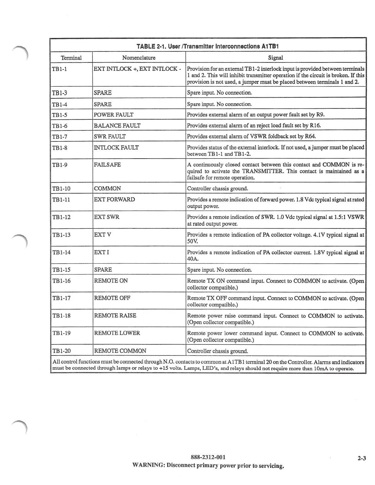
TABLE
2-1.
User
/Transmitter
Interconnections
A1TB1
Terminal
Nomenclature Signal
TBl
-1
EXT
IN1LOCK +,
EXT
IN1LOCK
- Provision for an external TB 1-2 interlock input is provided between terminals
1 and
2.
This will inhibit transmitter operation if the circuit is broken.
If
this
provision is not used, a jumper must
be
placed between terminals 1 and
2.
TBl-3
SPARE
Spare input. No connection.
TBl-4
SPARE
Spare input.
No
connection.
TBl-5
POWERFAULT
Provides external alarm
of
an output power fault set by R9.
TBl-6
BALANCE FAULT
Provides external alarm
of
an reject load fault set by R16.
TBl-7
SWRFAULT
Provides external alarm
of
VSWR
foldback set by R64.
TBl-8
IN1LOCK
FAULT
Provides status
of
the external interlock.
If
not used, a jumper must
be
placed
between
TBl-1
and
TBl-2.
TBl-9
FAILSAFE
A continuously closed contact between this contact and
COMMON
is re-
quired to activate the TRANSMITTER. This contact is maintained
as
a
failsafe for remote operation.
TBl-10
COMMON Controller chassis ground.
TBl-11
EXT
FORWARD Provides a remote indication
of
forward power. 1.8 V de typical signal at rated
output power.
TBl-12
EXTSWR
Provides a remote indication
of
SWR. 1.0 Vdc typical signal at
1.5:1
VSWR
at rated output power.
TBl-13
EXTV
Provides a remote indication
of
PA collector voltage. 4.1 V typical signal at
50V.
TBl-14
EXTI
Provides a remote indication
of
PA collector current. 1.8V typical signal at
40A.
TBl-15
SPARE
Spare input.
No
connection.
TBl-16
REMOTE ON
Remote
TX
ON
command input. Connect to COMMON to activate. (Open
collector compatible.)
TBl-17
REMOTE OFF
Remote
TX
OFF
command input. Connect to COMMON to activate. (Open
collector compatible.)
TBl-18
REMOTE RAISE
Remote power raise command input. Connect to
COMMON
to activate.
(Open collector compatible.)
TBl-19
REMOTE LOWER
Remote power lower command input. Connect to COMMON to activate.
(Open collector compatible.)
TBl-20
REMOTE COMMON
Controller chassis ground.
All control functions must
be
connected through N.O. contacts to common at A 1 TB 1 terminal 20
on
the Controller. Alarms and indicators
must
be
connected through lamps or relays to +15 volts. Lamps, LED's, and relays should not require more than lOmA to operate.
888-2312-001
2-3
WARNING: Disconnect primary power
prior
to servicing.