www.SteamPoweredRadio.Com
SECTION Ill
OPERATION
3.1.
Introduction
This section contains operating proce-
dures and information pertaining to identi-
fication, location, and function
of
the
controls and indicators
on
the HT line
of
Solid State
FM
Broadcast Transmitters,
setup, and operation procedures.
3.2.
Controls
and
Indicators
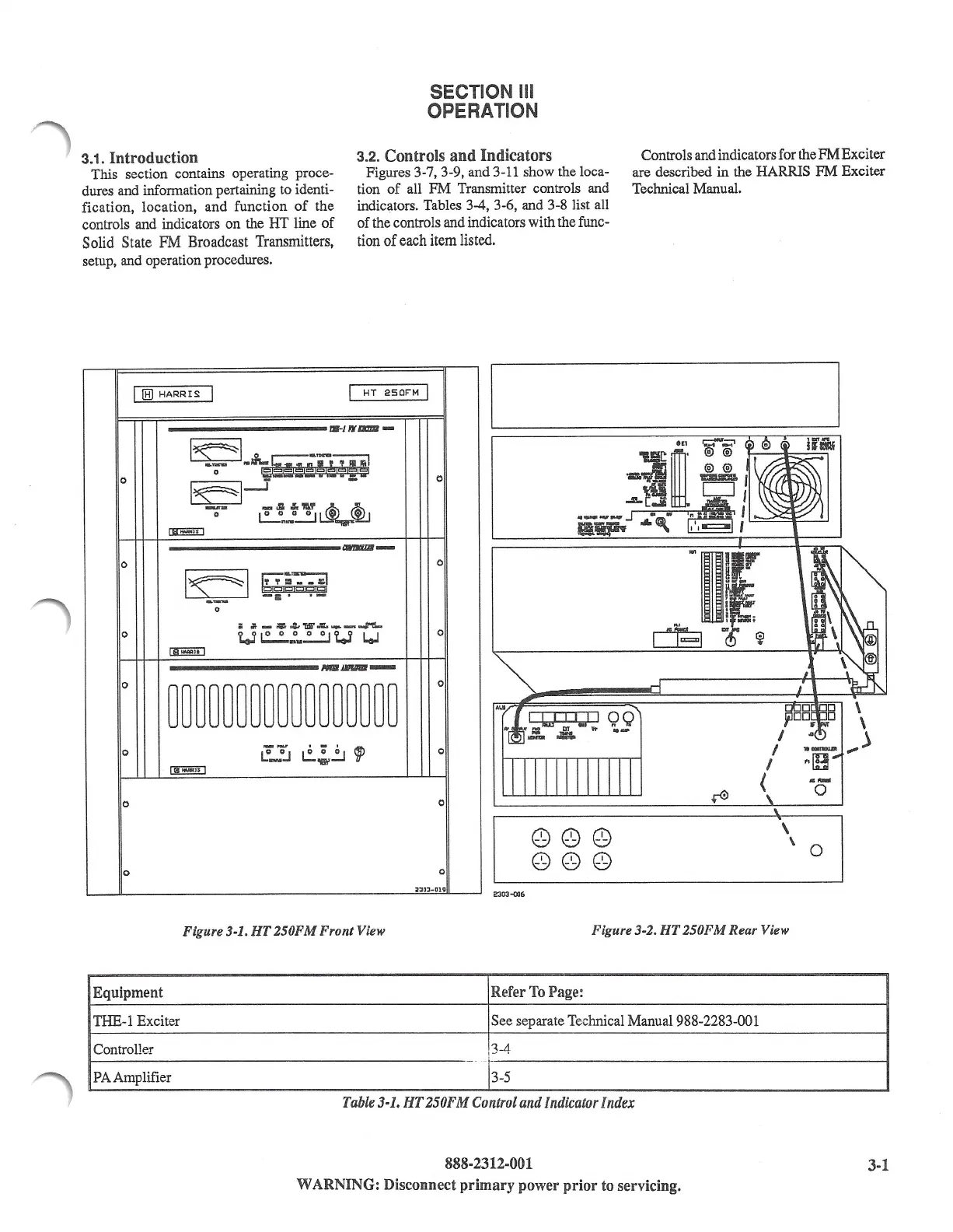
Figures 3-7, 3-9, and 3-11 show the loca-
tion
of
all
FM
Transmitter controls and
indic1,1tors.
Tables 3-4, 3-6, and 3-8 list all
of the controls and indicators with the func-
tion
of
each item listed.
Controls and indicators for the
FM
Exciter
are described in the HARRIS FM Exciter
Technical Manual.
I
lHl
HARRIS:
I
I
HT
250FM
I
IB-/Wamll-
l~I
,j_-•-:-;-;-;i
0
-';"
M ,:=!J,
,.a,+,
1,!,
0
l~l
_j -
~D
- ,II. ,I,"'-'
~<i2.J
0
l.:'..._".-~
~
--
0
0
l~I
~;
·a_
-
a1I
jgjgjc::Jj
□
j
;;
.
·-
0
=
~
- ;;.-...:,w.:.
.....
----
0
Ul!.!..!'
..
~U
LoJ
0
~
---
0
~~~~~~~~~~~~~~~~~
0
0
i:_°J
~~~
9P
0
I
IBI-W¥l
l$ 1
0
0
'\
•
\
\ 0
0
0
iZ:JOJ-OHil
2303-0'.!6
Figure 3-1.
HT
250FM Front View
Figure 3-2.
HT
250FM
Rear View
Equipment
Refer
To
Page:
THE-1 Exciter
See separate Technical Manu
al
988-2283-001
Controller
!3-4
PA
Amplifier
3-5
Table
3-1.
HT
250FM
Control
and
Indicator
Index
888-2312-001
3-1
WARNING: Disconnect primary power
prior
to servicing.