www.SteamPoweredRadio.Com
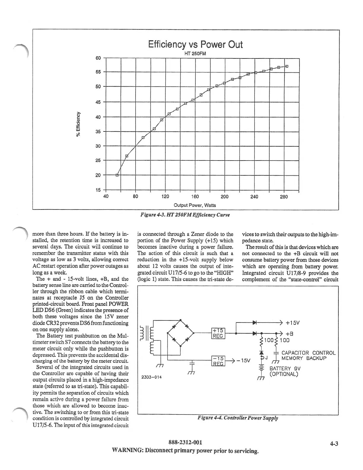
Efficiency
vs
Power
Out
HT250FM
60
55
50
_1:;.,-.'
a-s-EJ
_.....,e--
.....
r'...,,.
CYA
l
✓"
45
Sl
v'"
>.
0
40
C:
Q)
·13
!E
w
35
:al!
0
30
25
.,,z
1ft
)A
✓
-
/'
pi'/
I
I
20
I
~
15
40
80
120
160
200 240
280
more than three hours.
If
the battery is in-
stalled, the retention time is increased to
several days. The circuit will continue to
remember the transmitter status with this
voltage
as
low
as
3 volts, allowing correct
AC restart operation after power outages as
long
as
a week.
The + and - 1~-volt lines, +B, and the
battery sense line are carried to the Control-
ler through the ribbon cable which termi-
nates at receptacle J5 on the Controller
printed-circuit board. Front panel
POWER
LED DS6 (Green) indicates the presence
of
both these voltages since the 15V zener
diode CR3 2 prevents DS6 from functioning
on
one supply alone.
The Battery test pushbutton on the Mul-
timeter switch S7 connects the battery to the
meter circuit only while the pushbutton is
depressed. This prevents the accidental dis-
charging of the battery by the meter circuit.
Several
of
the integrated circuits used in
the Controller are capable
of
having their
output circuits placed in a high-impedance
state (referred to
as
tri-state). This capabil-
ity permits the separation
of
circuits which
remain active
du.ri.ng
a power failure from
those which are allowed to become inac-
tive. The switching to or from this tri-state
condition is controlled by integrated circuit
Ul
7 /5-6. The input
of
this integrated circuit
Output Power, Watts
Figure 4-3.
HT
250FM Efficiency Curve
is connected through a Zener diode to the
portion
of
the Power Supply (+15) which
becomes inactive during a power failure.
The action
of
this circuit is such that a
reduction in the + 15-volt supply below
about 12 volts causes the output
of
inte-
grated circuit U17 /5-6 to go to the "HIGH"
(logic
1)
state. This causes the tri-state de-
2303-014
vices to switch their outputs to the high-im-
pedance state.
The result
of
this is that devices which are
not connected to the +B circuit will not
consume battery power from those devices
which are operating from battery power.
Integrated circuit
Ul
7 /8-9 provides the
complement
of
the "state-control" circuit
-15V
+15V
+B
100
100
T
CAPACIT
.
OR
CONTROL
J
rt,
MEMORY
BACKUP
=
BATTERY
9V
,h
(OPTIONAL)
Figure
4-4.
Controller Power Supply
888-2312-001
4-3
WARNING:
Disconnect
primary
power
prior
to
servicing.