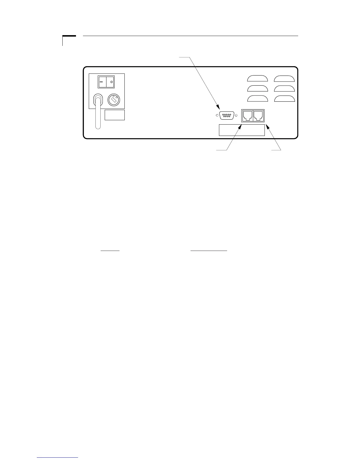
Figure 9. External Interface
External devices that can be attached to the Pump 33 include external valves, pump
chain, and TTL devices. See the appropriate appendixes for specification details on
attaching devices.
Attaching a Pump Chain
On the back of the pump are two telephone jack type connectors. These are the RS-
232 ports. Looking at the back of the pump, the connector on the right is port 1 and
the left is port 2. Attach the RS-232 connectors in the appropriate port according to
the following chart:
Device Port Number
Computer 1
Pump Chain 2
Configuring the Pump Chain
After pressing SET and 1, the Remote LED will blink, indicating the pump is request-
ing its pump chain configuration:
1. First, the display will show “Adr:nn”, with the colon blinking, where “nn” is the
current pump chain address. Enter the 2 digit address assigned to the pump
and press ENTER. Note: Each pump in the chain needs a unique address.
2. Next, the display will show “b:nnnn”, with the colon blinking, where “nnnn” is
the current baud rate. Use the 1 key to select between the supported baud
rates: 300, 1200, 2400 and 9600; then press ENTER. Note: Each pump in the
chain must have the same baud rate.
See the section on Pump Chain Commands for pump chain control information.