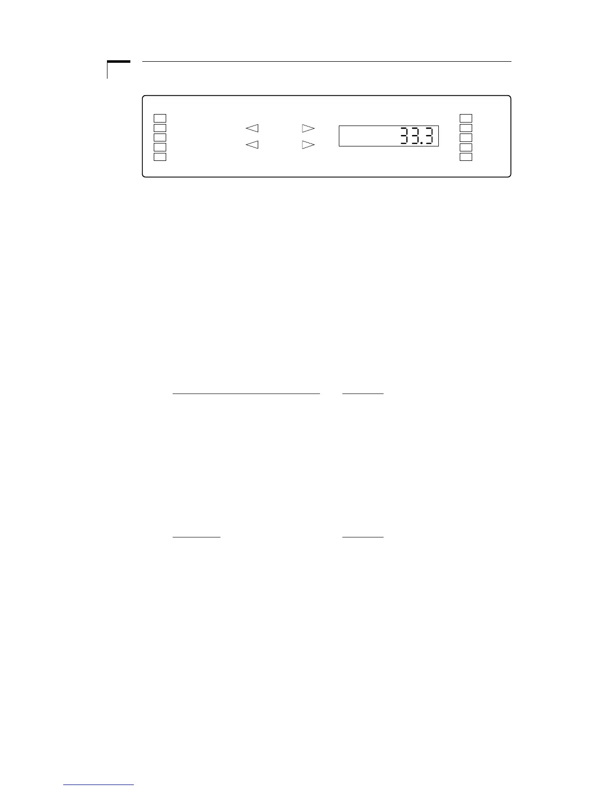
The user interface consists of a display area and a keypad. The display consists of a 5
digit LED display and 14 LED indicators. The display will be showing either the default
display or an informational message. The two syringes are referred to as Syringe 1 and
Syringe 2. Syringe 1 is located towards the front and Syringe 2 is located towards the
rear. Rate 1 refers to the set flow rate of Syringe 1 and Rate 2 refers to Syringe 2.
By default, the display will be showing Rate 1. Informational messages are shown
when the user queries another data value by pressing the corresponding key, or when
the pump is alerting the user to a problem. Such problems are a value out of range
(oor) or the pump stalling (StALL).
The 14 LED indicators are divided into three sections: Pump mode and state, syringe
directions, and units of value being displayed. See Figure 2.The LED indicators are
as follows:
Pumping Mode and State LEDs
Meaning
Auto Stop Pump is in Auto Stop mode
Proportional Pump is in Proportional mode
Continuous Pump is in Continuous mode
Remote Pump Chain communication
Run At least one motor is operating
Syringe Directions LEDs
Comprising of 4 indicators, these LED’s indicate the direction of the syringes when
illuminated. When blinking, indicates the corresponding motor is stalled, or data per-
taining to that syringe is being entered.
Unit LEDs
Meaning
ml/mn milliliters per minute
µl/mn microliters per minute
ml/hr milliliters per hour
µl/hr microliters per hour
mm millimeters
Figure 2. User Interface