Publication 5390-001 Revision B
15
Harvard Apparatus Model 33 Twin Syringe Pump User's Manual
External Control and Interfaces
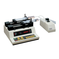
Attaching a Valve Control Accessory Box
Attach the valve control cable to the pump’s accessory valve connection (see Figure
9). Refer to the Valve Control Box section.
TTL Devices
The pump does not need to be configured to attach a TTL device. To attach a TTL
device, simply plug the appropriate TTL connector into the 9 pin connector on the
rear of the pump. See Appendix E for wiring specifications.
Foot Switch Input
Used to start and stop the pump. Pressing the foot switch performs the same function
as pressing the RUN/STOP key on the keypad. The foot switch connector allows
remote or automated operation of the pump.
Timer Input
Opening the timer input starts the pump. Closing the timer input stops the pump.
The timer input allows for an externally controlled pumping interval.
Pumping Direction Input
Sets the direction of pumping. Opening the directional input sets syringe 1 to
infuse. Closing the input sets syringe 1 to refill. The pumping direction input is
not recognized when data is being entered from the keypad. Syringe 2 changes
direction appropriately. Also, the valve control output is set appropriately.
Directional Indicator Output
The Directional Indicator output is an indicator of the direction of pump travel. When
the output is a logical high, syringe 1 is set to infuse. A logical low indicates refill. A
valve attached to this output enables automatic selecting of infuse and refill vessels.
Running Indicator Output
Provides a signal to another device indicating whether or not the pump is running.