EasyManuals Logo

Harvia C260 Instuctions For Use

Harvia C260
15 pages
To Next Page IconTo Next Page
To Previous Page IconTo Previous Page
Page #14 background imageLoading...
Page #14 background image
EN DE
14
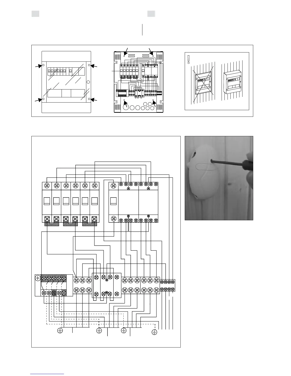
Figure 14. Internal connections of the power unit
Abbildung 14. Innere Anschlüsse der Leistungseinheit
Figure 15. Reset button for
overheating limiter
Abbildung 15. Rücksetzknopf des
Überhitzungsschutzes
F1
F2
F1
F2
F1
F2 F3
A1
A1
K3
K2
A2 A2
13 5
7
13 5
7
24 6
8
24 6
8
1
3
5
7
2
4
6
8
A1
K1
A2
1
2
3
4
5
6
7
8
910
11
13
12
N
L
K1
K2
K3
N
L1
N
L2
L3
L1
L2
L3
L1
L2 L3
N
400V 3N~
N
6A
TO CONTROL UNIT
ZUM STEUEREINHEIT
MAX 22 kW
MAX 34 kW
POWER UNIT
LEISTUNGSEINHEIT
K1: 63A
K2, K3: 25A
CONTACTORS
KONTAKTOREN
F1, F2 (16A )
F1, F2 (25A):
FUSES
SICHERUNGEN
Group I
GruppeI
Group II
GruppeII
GROUP I
GRUPPE I
GROUP II
GRUPPE II
ELECTRIC CENTRE
ELEKTROZENTRALE
Figure 13. Installation of the power unit on a wall
Abbildung 13. Installation der Leistungseinheit an der Wand
3.3.3. Electrical Connections
The electrical connections are made in accordance
with the connections diagram (Fig. 8).
3.3.3. Elektrische Schaltungen
Die elektrischen Anschlüsse werden dem Schaltbild
(Abb. 8) entsprechend vorgenommen.

Table of Contents

Other manuals for Harvia C260

Questions and Answers:

Question and Answer IconNeed help?

Do you have a question about the Harvia C260 and is the answer not in the manual?

Harvia C260 Specifications

General IconGeneral
BrandHarvia
ModelC260
CategoryControl Unit
LanguageEnglish

Related product manuals