7
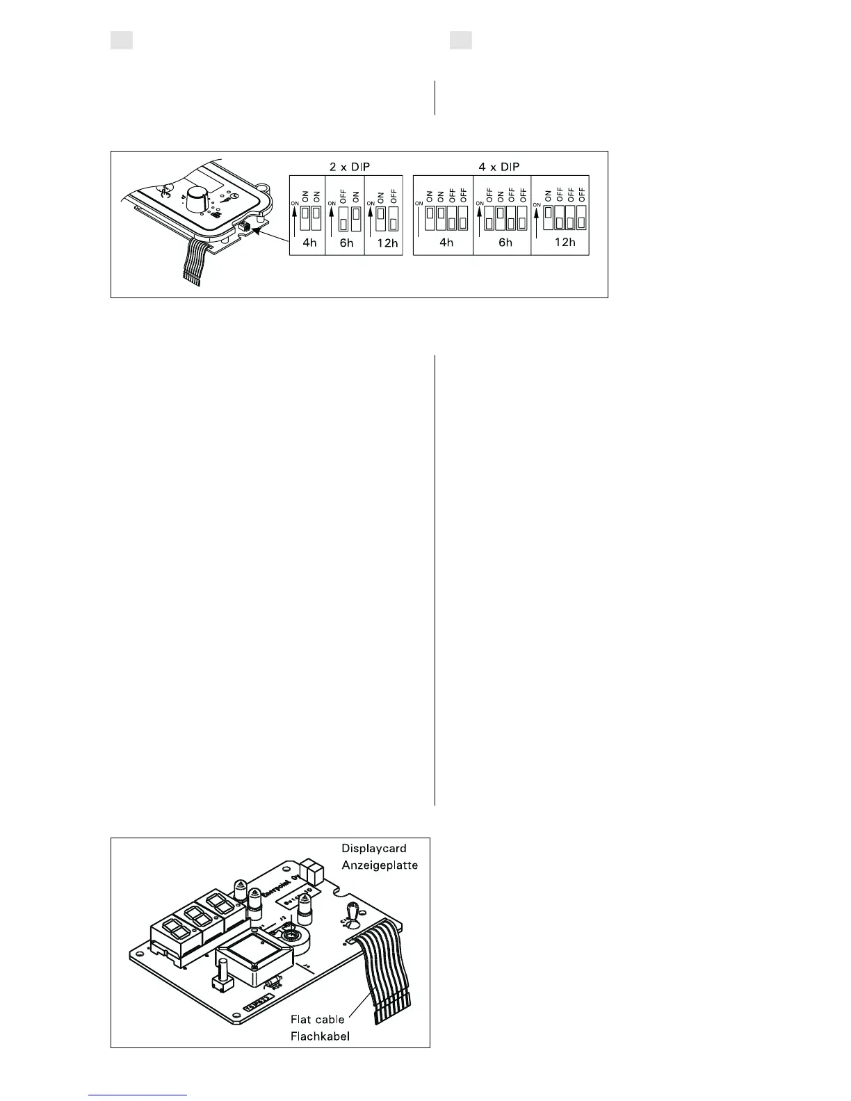
3.4. Changing the pre-set time
The pre-set time can be changed by means of the
DIP switches, which are located on the right side of
the unit’s upper circuit board, as follows:
3.4. Änderung der Einschaltzeit
Die Änderung der Einschaltzeit erfolgt mit den DIP-
Schaltern, die sich folgendermaßen am rechten Rand
der oberen Schaltkarte des Steuergeräts befinden:
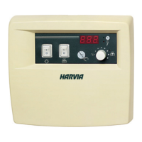
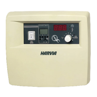
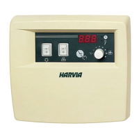
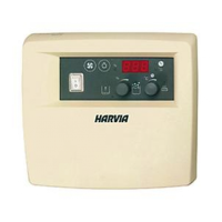
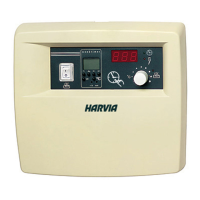
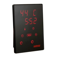
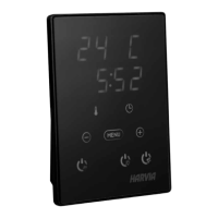
3.5. Service instructions for the Harvia
control unit
The operation of the control units is shared between
two electronic cards, which are connected by
means of a detachable flat cable.
The upper card is a display card (fig. 8), which
functions as a control and information device for
the user.
The lower card (fig. 9,) functions as a an electric
power card, which houses 2 pcs C150 three-phase
contactors that conduct electrical power to the
heater (in the C90 control unit there are a safety
contactor and three power relays, in the C80/1
control unit there are 2 pcs 1-phase contactors).
Both cards are screwed to parts of the box, so that
they are easily replaceable if the equipment develops
a fault. The electronic card exchange arrangement
is a faster and always cheaper alternative to the
whole device having to be disconnected and
replaced.
NB! Cards must be replaced by a qualified
electrician, with the proper precautions taken!
The display card must be replaced if
• the temperature display is acting oddly, i.e. it
shows or continues to show an obviously
untrue reading
• indicator lights 6, 7 and 8 are not working in
accordance with instructions for use
• setting the pre-set time, in accordance with
the instructions for use, proves unsuccessful
• programmed timings do not function properly
3.5. Wartungsanleitung für das
Harvia-Steuergerät
Die Funktionen der Steuergeräte sind auf zwei
im Gerät befindliche Elektronikplatten verteilt, die
miteinander durch einen entfernbaren Flachkabel-
anschluß verbunden sind.
Die obere Platte ist eine Anzeigeplatte (Abb. 8), die
dem Benutzer als Einstell- und Informationsgerät dient.
Die untere Platte (Abb. 9) dient zur Einstellung
der Leistung, über ihre 3-Phasen-Kontaktgeber
(C150; 2 Stk) wird die elektrische Leistung zum
Ofen geleitet (im Steuergerät C90 befinden sich
ein Sicherheitskontaktor und 3 Leistungsrelais, im
C80/1 Steuergerät befinden sich 2 Stk 1-Phasen-
Kontaktgeber.
Beide Platten sind mit Schrauben an Gehäuseteilen
befestigt und leicht austauschbar, falls im Betrieb
des Geräts ein Fehler auftritt. Der Austausch der
Elektronikplatten ist stets schneller und billiger als
der Abbau des gesamten Geräts vom Anschlußkabel
und der Wechsel des Geräts.
Achtung! Der Austausch der Platten muß von einem
Fachmann und mit besonderer Vorsicht erfolgen!
Die Anzeigeplatte muß gewechselt werden, wenn
• die Temperaturanzeige defekt ist, d.h. falsche
Temperaturwerte anzeigt oder stehenbleibt
• die Kontrolleuchten 6, 7 und 8 nicht wie
in der Bedienungsanleitung angegeben
funktionieren
• die Einstellung der Vorwahlzeit nicht wie in
der Bedienungsanleitung angegeben möglich ist
• die programmierten Zeiten nicht stimmen
EN
DE
Figure 7.
DIP switches (Please
note! 12 hours only for
communal use / 4 and
6 hours for family and
communal use)
Abbildung 7.
DIP-Schalter (Achtung! 12
h nur für gewerbliche und
Vereinssaunen 4 h und 6
h für die Nutzung durch
Familien und gewerbliche
bzw. Vereinssaunen)
Figure 8.
Abbildung 8.

 Loading...