6
Holding the device in the upright position, mark the
locations for the two lower fastening screws (2
and 3) and follow the same procedure, except that
these screws should be screwed tightly in as far as
they go. See figure 4.
3.3. Installation of Sensor Box
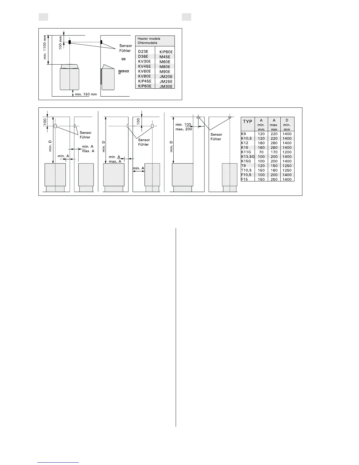
To control wall-mounted heaters by means of a
control unit, the sensor box connected to the unit
should be installed on the sauna room wall above
the heater on its centre line, running parallel to its
sides, and 100 mm from the ceiling. See fig. 5.
To control heaters fixed to the floor of the sauna
by means of the control unit C150, the sensor box
connected to the unit should be installed on the
sauna room wall above the heater, on the heater’s
centre line, 100 mm from the ceiling. Note! The
table also shows the heater’s maximum distance
from the wall on which the sensor box of the
thermostat has been installed.
The sensor box can also be installed above the
heater on the ceiling, at a distance of 200 mm from
the vertical line of the unit of the heater’s edge.
See Figure 6.
The cable enclosed with the thermostat is made
of silicon and can withstand temperatures of up
to +170 °C. The cable can be extended with
lower temperature cable having a corresponding
cross-section, as long as you ensure that after the
connection has been made the temperature to the
cable does not rise above +80 °C.
Die Steuereinheit kann an der obersten Schraube
hängen, bis sichergestellt ist, daß die Schraube in
der schmalen Führung des Rückteils eingerastet
ist. Für die beiden unteren Befestigungsschrauben
(2 und 3) werden die Bohrungen bei senkrecht
stehender Steuerzentrale markiert, und es wird wie
beschrieben verfahren, wobei jedoch die Schrauben
fest angezogen werden. Siehe Abbildung 4.
3.3. Installation des Fühlerkastens
Zur Steuerung von Saunaöfen mit Wandmontage
mit den Steuergeräten muß der an das Steuergerät
anzuschließende Fühlerkasten an der Saunawand
oberhalb des Saunaofens, auf der Mittelachse in
Breitenrichtung des Saunaofens 100 mm unterhalb
der Decke angebracht werden. Siehe Abb. 5.
Zur Steuerung von Saunaofen-Standmodellen mit
dem Steuergerät C150 muß der an das Steuergerät
anzuschließende Fühlerkasten an der Saunawand
oberhalb des Saunaofens, auf der Mittelachse des
Saunaofens 100 mm unterhalb der Decke ange-
bracht werden. Achtung! In der Tabelle ist auch der
max. Abstand des Ofen zu der Wand angegeben,
an der der Fühlerkasten angebracht wird.
Der Fühlerkasten kann auch oberhalb des Sauna-
ofens an der Decke in einem Abstand von 200 mm
von der Senkrechten im Mittelpunkt des Ofenrandes
angebracht werden. Siehe Abb. 6.
Das Kabel, das zusammen mit dem Thermostat
geliefert werden, ist aus Silikon und ist bis 170 °C
wärmebeständig. Zur Verlängerung des Silikonkabels
können Kabel mit einem anderen Wärmeleitwert
verwendet werden, die einen entsprechenden
Querschnitt hat, sofern sichergestellt ist, daß
nach dem Anschluß die auf das Kabel einwirkende
Temperatur nicht über +80 °C steigt.
Figure 5.
The place of the sensor box of the control units in
connection with wall-mounted heaters.
Abbildung 5.
Lage des Fühlergehäuses des Steuergeräts bei
Saunaöfen mit Wandmontage.
Figure 6. The position of the sensor box of the control unit C150 in connection with heaters attached to the floor.
Abbildung 6. Lage des Fühlergehäuses des Steuergeräts C150 bei Saunaofen-Standmodellen.
EN
DE

 Loading...