COMMISSIONING MANUAL
____________________________________________________________________________________
__________________________________________________________________________________
Page 8/32
SOUND2.943.001-E.e
The microphone has to be placed under the mill at the ball’s impact point.
The impact point is situated more or less at the “four o’clock” position (120° to 140°).
Longitudinally, the area to monitor is situated at approximately 1 to 1.5m from the diaphragm,
or at 2/3 of the first chamber.
Figure 2 : Mill description
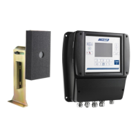
Figure 3 : Microphone placement (Ball’s impact)
The microphone interface must be installed closer to the mill in order to have the best capture
of the signal and in order to minimize the others mill influences when all mills are installed in
the same room.
The microphone support must be a solid construction because any accidental displacement
which could cause irremediable damage.
The microphone head is adjustable to 360°. A vertical or horizontal support can be used.
 Loading...