Do you have a question about the Haulotte Group HA 20PX and is the answer not in the manual?
Provides general warnings and guidance on manual usage, labels, and safety.
Details safety instructions for operators, environment, and machine usage.
Outlines residual risks associated with machine operation, including movement, electrical, and collision hazards.
Covers periodic inspections, machine suitability examination, and state of conservation checks.
Specifies requirements for major repairs, safety system adjustments, and use of original parts.
Details checks required after major disassembly, repair, or accident.
Presents the Beaufort Scale for wind force, used for weather condition communication.
Describes machine identification through the manufacturer's plate and serial number.
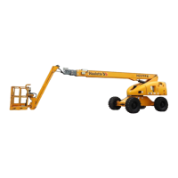
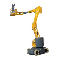
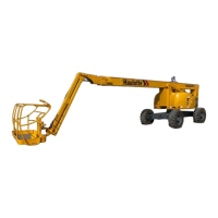
Illustrates and lists the main components of the self-propelled lift.
Defines the operational work areas for HA20PX and HA260PX models.
Provides detailed technical specifications for the HA20PX and HA260PX models.
Details the dimensional specifications of the HA20PX and HA260PX machines.
Categorizes and explains common labels found on the machine.
Explains the hydraulic system powering the machine's movements.
Details the electric power system and built-in safety features for machine protection.
Describes safety systems designed to prevent exceeding machine capacity.
Provides essential precautions for unloading, loading, and moving the machine.
Outlines essential operations and familiarization before the initial use of the machine.
Guides users on identifying and understanding controls on the turntable and platform panels.
Details critical checks required for the machine's movement zone and general appearance.
Explains the operation and instructions for the optional onboard generator.
Covers procedures for starting the machine's motor and performing initial movement tests.
Provides instructions for emergency lowering procedures when the operator is incapacitated.
Details rescue procedures using the standby electropump unit and uncoupling for towing.
General recommendations for maintenance operations under various conditions.
Outlines the maintenance plan, periodicity, service points, and consumables.
Details specific maintenance operations and instructions, including filter and reducer checks.
Describes overload, functional, and stability tests to be performed on the machine.
Lists and explains the functions of relays and fuses located in the turntable box.
Details the functions of various safety contacts integrated into the machine's systems.
Wiring diagram folio 01/05 for the machine's electrical system.
Wiring diagram folio 02/05 for the machine's electrical system.
Wiring diagram folio 03/05 for the machine's electrical system.
Wiring diagram folio 04/05 for the machine's electrical system.
Wiring diagram folio 05/05 for the machine's electrical system.
Hydraulic diagram for HA20PX model, reference B17074.
Hydraulic diagram for HA260PX model, reference P24340.
| Brand | Haulotte Group |
|---|---|
| Model | HA 20PX |
| Category | Lifting Systems |
| Language | English |