EasyManua.ls Logo

Hawker LIFEPLUS LPM3-48F-240Y User Manual

Hawker LIFEPLUS LPM3-48F-240Y
50 pages
To Next Page IconTo Next Page
Page #1 background imageLoading...
Page #1 background image
For local parts, sales and service, call toll-free 1-800-251-6560.
AM-HLPM3-OM
Rev AB September 2019
Model:
S/N:
AC Input Voltage
Installed by
Date
IMPORTANT
Read and understand your user’s manual before installing, operating, or servicing this
product.
DO NOT DESTROY THIS BOOK
Battery Charger
with Wireless Communications
Owner’s Manual
LIFEPLUS
MOD3
Models: LPM3 (Standard and Flex)
LPM3C (CEC)

Table of Contents

Question and Answer IconNeed help?

Do you have a question about the Hawker LIFEPLUS LPM3-48F-240Y and is the answer not in the manual?

Hawker LIFEPLUS LPM3-48F-240Y Specifications

General IconGeneral
Input Voltage208-240 VAC
Input Frequency50/60 Hz
Output Voltage48 VDC
Output Current240 A
Efficiency>90%
Operating Temperature0°C to 40°C
Storage Temperature-20°C to 60°C
Cooling MethodForced Air
Protection FeaturesOver voltage, over current, short circuit, over temperature
Weight28 kg

Summary

Important Safety Instructions

TECHNICAL INFORMATION

Part Number and Model Identification

Identifies charger characteristics via UL Model and Part Numbers.

INSTALLATION

Location

Guidance on choosing a suitable location for charger installation.

Wall and Floor Mounting

Mounting requirements for wall/floor cabinet chargers.

Electrical Connection Procedures

Instructions for making electrical connections to the charger.

Input Power Connection

Steps for connecting the input power to the charger terminals.

AC Circuit Protection Requirements

Requirements for branch circuit protection and disconnect methods.

Operation Overview

General Charger Features

Overview of LIFEPLUS MOD3 series charger capabilities and compatibility.

Automatic Start Charge

Explains the automatic charging initiation process after battery connection.

Charging Current

Describes how charging current is determined and adjusted during the charge.

Operating Instructions Overview

Control Panel Layout

TFT LCD Display Function

Displays charger operation information and menus.

Control Panel Navigation Buttons

Buttons used to navigate through menus and options.

Stop and Start Button Function

Controls for starting and stopping the battery charge.

Control Panel LED Indicator

Visual indicator for charger status (fault, charging, idle, complete).

Control Panel USB Port

Port for logging data, updating firmware, and saving parameters.

Charger Idle Screen Display

Main Menu Display Screen

Accessing the Main Menu

System Setup Options

Charge Profile Configuration Settings

Battery Capacity Setting

Adjusts battery AH capacity for start/finish rates, or uses BBWC data.

Battery Temperature Regulation

Adjusts regulation voltages based on battery temperature, uses BBWC if available.

Setting the Charge Profile

Equalization Configuration

Equalize Day Selection

Selects the day(s) of the week for equalization.

Equalize Time and Delay

Sets the time of day and delay for equalization charges.

Start Charge Configuration Options

Charge Delay Settings

Configures delays for starting a charge cycle by time of day or after battery connection.

Post Charge Configuration Settings

Charger Configuration Options

Cabinet Bay Size Selection

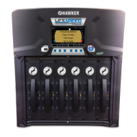
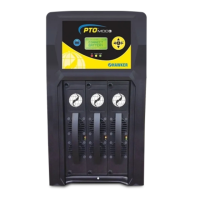
Selects the cabinet bay size (3, 6, or 12 Bay).

BBWC Communication Settings

Battery Charging Process

Charger Idle Display Information

Information shown on the display when the charger is idle.

BBWC Connection Process

Charging Display Information

End of Charge Display Status

Equalization Charging Modes

Manual Equalize Procedure

How to manually start an equalize charge cycle.

Automatic Equalize Procedure

How equalize charges start automatically based on programming.

Charger Information Display

Troubleshooting Faults

Fault: Battery Disconnects While Charging

Fault occurs if battery is disconnected without stopping the charge cycle.

Module Status Display Overview

Module LED Status Interpretation

Interprets LED indicators on modules to determine their status.

Mounting Dimensions Guide

3 Bay Charger Mounting Dimensions

Diagrams and measurements for mounting the 3-bay charger.

6 Bay Wall Mounting Dimensions

Maintenance and Service Guidelines

Component Location Identification

Specifications: 208/220/240V Chargers

Specifications: 440V Chargers

Specifications: 480V Chargers

Specifications: 600V Chargers

Related product manuals