Do you have a question about the Hayward AquaTrol and is the answer not in the manual?
Warns about high voltage hazards and safety precautions for qualified technicians.
Initial display indicates Metric Mode; press 'Diagnostics' to start change.
Temperature changes to Fahrenheit; finalize by cycling switch to 'Super Chlorinate' then 'Auto'.
Display shows number followed by 'P', indicating 'Desired Output %'.
Adjusting switch to 'AL-0' and then '3400' to restore average salt level.
Explains when 'Check Salt' and 'Inspect Cell' LEDs flash or stay ON based on salt levels.
Inspect cell for deposits; clean if necessary; check pages 17-19 for cleaning.
Guidance on testing salt levels and adding salt if below the recommended range.
Cycle switch to reset; press 'Diagnostics' to view instant salt reading.
Move switch to 'Super Chlorinate' then 'Auto' when stable; verify new reading.
Resetting the average salt by cycling the switch from 'Off' to 'Auto'.
Using the Diagnostics button to view the Instant Salt level.
Cycling the switch to 'Super Chlorinate' and back to 'Auto'.
Explains how the 'Desired Output %' dial controls cell operation time.
Rotate dial left to decrease, right to increase chlorine output.
Advises testing water chemistry if chlorine output doesn't increase.
Explains when 'High Salt' LED is ON and 'HI' display condition due to amperage.
Verify salt, cell model; drain/refill for excessive salt levels.
Displays the maximum amperage before shutdown for the T-CELL-5 model.
Provides formulas to calculate water needed for removal and inches to drain.
Demonstrates calculation and advises limiting water level reduction to six inches.
Explains 'No Flow' LED flashing on start-up vs. being ON due to flow detection issues.
Steps for a flashing 'No Flow' LED: check pump priming and water flow.
Steps for a solid 'No Flow' LED: check flow switch connection and wire integrity.
Verifies 12" of straight pipe before the flow switch and orientation.
Instructions to check the control box for corrosion or damage before replacing the switch.
Measures 18-33 VDC between black and red wires on the main board.
Procedure to remove and reseat the DSP board to resolve display issues.
Checks 115-125 VAC at input terminal TB1.
Measures 20-24 VAC between yellow wires.
Verifies power at the GFCI or standard receptacle if TB1 voltage is incorrect.
Measures resistance between Blue/White and Violet/Gray wires for transformer fault.
Tests continuity of the 20 amp yellow ATO style fuse.
Verifies 10-14 VAC between the Orange wire and the Green Grounding lug.
Identifies the PCB-Trol and Rectifiers (GLX-DRK) for potential replacement.
Specifies operating range and explains LCD readings like 'COLD' and 'HOT'.
Notes sensor failure causes high temp readings; output is scaled by temperature.
Discusses cleaning frequency factors and guide on inspecting for deposits.
Technique for revealing deposits; safety warnings for acid cleaning.
Initial step to use a water hose to remove small debris from the cell.
Using a 1:4 acid to water solution for a 15-minute soak on each end.
Inspecting the cell, repeating if needed, and resetting the 'Inspect Cell' LED.
Instructions for using the stand with acid solution for soaking and inspection.
Press diagnostic button to reset 'Inspect Cell' LED timer and average salt if needed.
Explains the timer tabs representing 15-minute intervals for pump operation.
Describes 'Pump Timer Override', 'Auto Timer Mode', and 'Pump Timer Manual Off'.
Checking if the displayed model number (AL-6 or AL-7) is correct.
Verifying continuity between brown wires at J1 on the PCB.
Recommends replacing the time clock if continuity is absent.
Verifying 115-124 VAC between terminals E5 and E6 on the PCB.
Verifying 115-125 VAC at the pump receptacle on the bottom of the Trol.
Guidance on replacing the receptacle or PCB based on voltage readings.
Assesses salt level, cell cleanliness, and guides on resetting average salt.
Checks salt reading against independent tests for customer's or new cell.
Checks salt level and cell cleanliness for 'High Salt' LED issues.
Action to lower salt level to 3200ppm if it exceeds the recommended range.
Procedure to reset average salt level as part of the troubleshooting process.
Wait after start, check LED, verify flow switch installation and connection.
Check for blockage/pressure; replace switch if issues persist.
Check pump/valves; verify flow switch plumbing and arrow alignment.
Check wire damage, test switch, replace PCB if necessary.
Verify DC voltage, 120VAC input, and yellow wire AC voltage.
Ohm out transformer, check fuse continuity, replace rectifiers as needed.
Verify model, check brown wire continuity, and PCB voltage.
Check pump receptacle voltage and troubleshoot pump control.
Table detailing pounds of salt needed for various pool sizes and target ppm.
Instructions on properly adding salt to the pool for distribution.
Control operation time with %; discuss calculated vs. actual salt level differences.
Increase % for aging cells; use Super-Chlorinate for production boost.
Explains the components of serial numbers starting from 08-05-2011.
Explains the components of serial numbers starting from 11-01-2001.
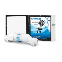
| Model | AquaTrol |
|---|---|
| Type | Salt Chlorine Generator |
| Pool Type | Above Ground |
| Voltage | 120V/240V |
| Display | Digital |
| Salt Level | 2700-3400 ppm |
| Weight | 15 lbs |
| Warranty | 1 Year |