Do you have a question about the Hayward TC Series and is the answer not in the manual?
Details limitations on using products with compressible fluids and in air or gas service.
Covers fluid velocity, piping support, temperature effects, and installation into metal piping systems.
Instructions for storing and moving the valve before installation, emphasizing care to avoid damage.
Procedures for connecting the valve to the piping system, including end connector types and reassembly.
Initial steps to bring the system online after installation, including purging air and checking operation.
Recommendations for periodic checks, leak inspections, and operating infrequently used valves.
Detailed steps for disassembling, repairing, and reassembling the valve, including O-ring replacement.
Solutions for leaks between body/connector and ball/seat, and for damaged components.
Solutions for excessive cycles, water hammer, solids, cavitation, and no flow.
Table detailing operating temperatures for PVC, CPVC, PP, and PVDF materials.
Specifications for maximum system flow velocity and flow capacity (Cv) by size.
Graphs showing operating pressures at elevated temperatures for PVC, CPVC, PP, and PVDF materials.
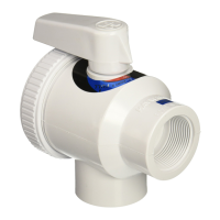
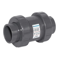
Diagram illustrating the components of the True Union Ball Check Valve.
Details the two-year warranty, limitations, sole obligation, and maximum liability.
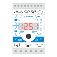
| Category | Control Unit |
|---|---|
| Manufacturer | Hayward |
| Enclosure Rating | NEMA 3R |
| Series | TC |
| Product Line | Time Clock |
| Voltage Rating | 120/240 VAC |
| Maximum Load Current | 40A |
| Mounting | Surface |
| Certifications | UL Listed |