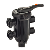
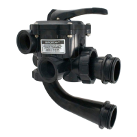
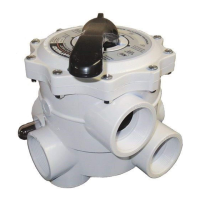
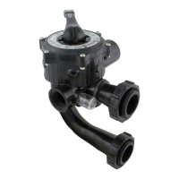
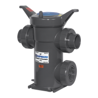
The Hayward SelectaFlo™ Hi-Efficiency Valve is a crucial component designed for use with Hayward ProGrid DE series filters, offering a comprehensive solution for managing water flow in pool filtration systems. This "How To Guide" provides detailed instructions for its installation, operation, and maintenance, ensuring optimal performance and longevity.
Function Description:
The primary function of the SelectaFlo™ valve is to control the direction of water flow within a pool's filtration system, enabling various operational modes essential for pool maintenance. It acts as a multi-port valve, allowing users to switch between different functions such as filtering, backwashing, recirculating, and draining, all from a single control point. The valve is engineered for high efficiency, contributing to improved filtration performance and potentially reducing energy consumption.
Important Technical Specifications:
- Compatibility: Specifically designed for Hayward ProGrid DE series filters.
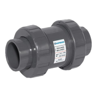
- Port Connections: The Pump, Return, and Waste ports are 2" SKT (Socket) x 2½" Spigot (solvent weld) connections, facilitating secure and leak-free plumbing.
- Built-in Unions: The valve features built-in unions, simplifying the attachment to the filter and allowing for easier installation and removal.
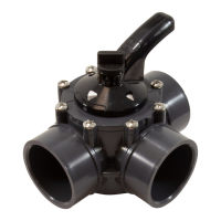
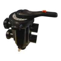
- Handle Mechanism: Equipped with a robust handle and latch system for secure positioning and easy operation. The handle includes a button that must be depressed to release the latch, preventing accidental changes in valve position.
- Internal Components: The valve's internal structure includes a valve shaft with O-rings, a valve hub handle, seal carriers, and a waste port seal carrier assembly, all designed for durability and efficient sealing.
- Sight Glass: Includes a sight glass with a gasket (SPX0710MA, SX200Z9) to visually monitor the clarity of backwash water, indicating when the filter is clean.
- Seal Kits: Replacement O-ring seal kits (SPX0425Z2, SX200Z4PAK2) are available for the shaft, cover, waste port seal, and unions, ensuring long-term maintainability.
- Material: Constructed from durable materials suitable for pool environments, resistant to chemicals and UV exposure. The valve body (SPX0425A) is designed for robust performance.
Usage Features:
The SelectaFlo™ valve offers four distinct operational positions, each serving a specific purpose in pool maintenance:
-
FILTER (Normal Filtration):
- Flow Direction: Pump → Through Filter → Return.
- Purpose: This is the standard operating mode for daily pool filtration and vacuuming the pool through the filter. Water is drawn from the pool by the pump, passes through the filter media to remove debris, and then returns to the pool.
-
BACKWASH (Filter Cleaning):
- Flow Direction: Pump → Through Filter (in reverse) → Waste.
- Purpose: Used for cleaning the filter media. Water flows in the opposite direction through the filter, dislodging trapped debris, which is then directed out to the waste line. The sight glass allows users to monitor the water clarity during backwash, indicating when the filter is sufficiently clean. Always turn off the pump before changing to this position.
-
RECIRCULATE (Bypassing Filter):
- Flow Direction: Pump → Through Valve → Return.
- Purpose: This mode bypasses the filter media, allowing water to circulate directly from the pump back to the pool. It is useful for mixing chemicals without filtering, or when the filter is undergoing maintenance and circulation is still desired.
-
WASTE (Draining/Vacuuming to Waste):
- Flow Direction: Pump → Through Valve Only → Waste.
- Purpose: This position is used for vacuuming directly to the waste line, lowering the pool level, or completely draining the pool. Water is drawn from the pool and sent directly to waste without passing through the filter or returning to the pool.
Handle Installation:
The installation of the handle is a straightforward process:
- Alignment: Secure the handle to the valve body by aligning the thin tooth on the handle with the corresponding thin slot on the valve shaft.
- Fastening: Insert the screw into the handle and tighten it using a 3/8" socket and ratchet.
- Covering: Align and press the handle plug into the slot to cover the screw, providing a clean finish and protecting the screw from corrosion.
Valve Assembly:
The assembly of the valve involves several key steps to ensure proper sealing and function:
- Waste Port Seal Carrier Installation: Align the locating features (arrows) on the waste port seal carrier with those on the bottom of the valve body and install it.
- Seal Lubrication and Installation: Lubricate the inward-facing seals with silicon lube. Install the seal carriers by firmly pressing them down into their respective slots. This ensures a tight seal and smooth operation.
- Hub Assembly Installation: Install the Hub Assembly into the valve body by aligning its locating features (arrows).
- Cover Installation: Fold the handle down and install the cover by aligning the cover and hub locating features.
Operating Instructions:
Operating the SelectaFlo™ valve is designed to be user-friendly, with a critical safety precaution:
- Safety First: ALWAYS turn off the pump before changing the valve position. This prevents damage to the valve and the pump.
- Changing Positions:
- Depress the button on the handle to release the handle latch.
- With the button depressed, rotate the handle to the desired valve position (Filter, Backwash, Recirculate, or Waste).
- Release the button on the handle, allowing the handle to lock securely into the new position.
Maintenance Features (Winterization Disassembly):
Proper winterization is essential for protecting the valve from freezing damage. The disassembly process is designed for ease of access to internal components for inspection and storage:
- Safety: Turn off the pump before disassembling the filter control valve.
- Lock Ring Removal: Rotate the lock ring counterclockwise to remove the cover assembly.
- Cover Assembly Removal: Remove the cover assembly. If it's difficult to remove, gently rock the base of the handle while pulling up.
- Hub Assembly Removal: Use the handle to lift the entire hub assembly out of the valve body.
- Seal Carrier Inspection: Remove the seal carriers and thoroughly check them for any signs of wear or damage.
- Replacement: Replace any worn or damaged parts, such as O-rings or seal carriers, with genuine Hayward replacement parts to ensure optimal performance in the next season.
The Hayward SelectaFlo™ Hi-Efficiency Valve is a robust and versatile component, designed for ease of use and long-term reliability in pool filtration systems. Its clear operational modes, simple installation, and straightforward maintenance procedures make it an indispensable part of any Hayward ProGrid DE filter setup.