Hayward Flow Control www.haywardflowcontrol.com 1-888-HAY-INDL (1-888-429-4635)
TCIS Rev D 5/15/18
Pg. 3 of 11
1. INSTALLATION:
1.1. Transporting the Valve:
Valve should be stored inside factory packaging until product is ready to be installed. Packaged valve should be stored indoors, at room
temperature, and out of direct sunlight. Avoid storing packaged valve in location where packaging may become wet. Valve should be moved
as close to installation site as possible prior to removing from packaging. Do not cut through tape on box any more than necessary to avoid
damaging valve. After removing valve from carton, care must be taken not to damage valve or to allow debris to enter valve.
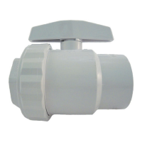
1.2. Installing the Valve into a System:
1.2.1. Remove valve from packaging.
1.2.2. Verify that product is defect free and meets specifications.
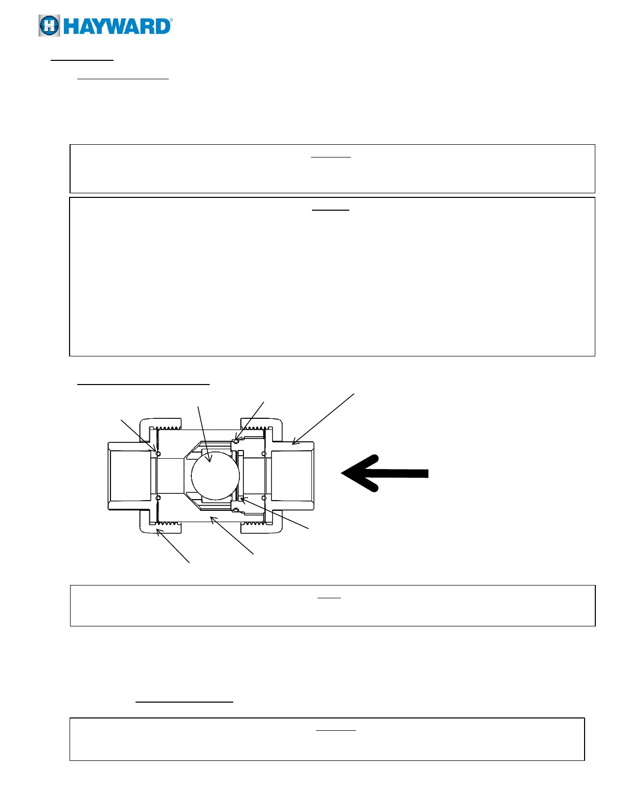
1.2.3. Remove the nut and end connector by rotating the nuts counter clockwise. Verify end connector o-rings are installed in their
respective grooves.
1.2.4. Place nut over pipe end so that it can engage the end connector once the end connector is connected to the pipe end.
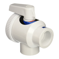
1.2.4.1. Threaded End Connectors:
1.2.4.1.1. Wrap male threads of pipe end with PTFE tape for seal on threaded joints.
WARNING
Do not use “pipe dope”, liquid sealant, or thread sealant on any PVC, CPVC, PP, or PVDF threaded connections. Pipe dope and
thread sealants may react with the PVC, CPVC, PP, or PVDF, weakening the material and potentially resulting in failure of the
joint, product damage, property damage, personal injury, or even death.
CAUTION
Do not install valve directly to pump outlet. Allow a length of at least 10 pipe diameters between pump outlet and valve.
Do not install valve directly after a reducer / expansion fitting. Install at least 10 pipe diameters from an expansion or reducing
fitting.
Pipe must be supported upstream and downstream of the valve. Sound piping system design principles should be applied
when installing this valve.
Do not install valve directly into a metal system (see pg. 2). Wherever installation of thermoplastic valves into metal piping
systems is necessary, it is recommended that at least 10 pipe diameters in length of thermoplastic pipe be installed upstream and
downstream of the thermoplastic valve.
When lifting valve do not lift by the handle.
WARNING
System must be depressurized and drained prior to installing valve or performing maintenance. Failure to depressurize and drain
system prior to installing or maintaining valve may result in product damage, property damage, personal injury, or even death.
NOTE
Hayward TC Series True Union Ball Check Valves with standard balls are uni-directional. There is a flow arrow marked on the
valve to indicate proper flow direction.
 Loading...