USE ONLY HAYWARD GENUINE REPLACEMENT PARTS
12
USE ONLY HAYWARD GENUINE REPLACEMENT PARTS
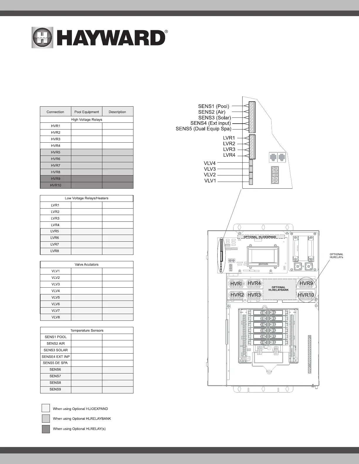
Connection Table
The HLBASE includes 4 high voltage relays, 4 low voltage/heater relays, 4 valve outputs and 4 temperature sensor inputs. Additional relays and inputs/outputs
can be added using an HLRELAYBANK, HLIOEXPAND or HLRELAY(s) (see Accessories) . When wiring pool equipment to the OmniLogic, keep a record of all con-
nections. You’ll need to record which input/output is used and what equipment is attached. To aid in this process, use the table below. To identify the various
inputs/outputs, refer to the diagram on the side of the table. After attaching equipment to the OmniLogic, fill in the appropriate information in the table.
Connection Table