USE ONLY HAYWARD GENUINE REPLACEMENT PARTS
4
Mounting the Equipment
OmniLogic Enclosure
The OmniLogic is contained in a raintight enclosure that is suitable for outdoor mounting. The control must be mounted a minimum of 6 ft. (2 meters) horizontal
distance from the pool/spa (or more, if local codes require). The OmniLogic is designed to mount vertically on a flat surface with the knockouts facing downward.
Because the enclosure also acts as a heat sink (disperses heat from inside the box), it is important not to block the four sides of the control. Do not mount the
OmniLogic inside a panel or tightly enclosed area.
When selecting a location, note that the standard cables supplied with the included flow switch and temperature sensors, as well as optional accessories like
Hayward TurboCells and actuators are all 15 ft. (5m) long. Try to mount the OmniLogic at a height where the touchscreen can be accessed easily.
The OmniLogic weighs close to 60lbs. and will require two people to position and install. Select the proper location and mounting hardware given the size and
weight of the unit. The OmniLogic mounting brackets require a total of 6 mounting bolts to fasten the OmniLogic to the mounting surface.
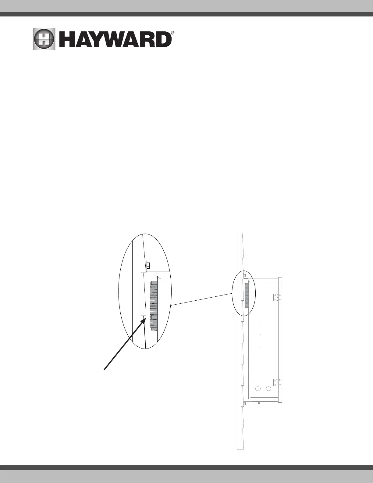
Note that there is a heat sink on the back of the enclosure. Refer to the following information regarding the OmniLogic heat sink:
In all cases the heat sink on the back of the OmniLogic panel should not contact the wall behind the panel. This restricts air flow and makes the heat sink less
efficient. A minimum separation of 1/8” (except for vinyl siding) should be maintained between any heat sink pin and the siding on the wall behind the enclosure.
In the case of a flat wall the mounting flanges on the enclosure ensure that the minimum clearance is maintained. For shingles, clapboards or other siding with
a non-flat profile, the installer must ensure the minimum separation. Refer to the diagram on below.
Special Installation Instructions for Vinyl Siding
IMPORTANT: The heat sink on the back of the OmniLogic panel cannot be allowed to contact vinyl siding; during normal chlorinator operation the heat sink pins
get warm enough to deform vinyl siding on contact. An increased minimum separation of 3/8” should be maintained between any heat sink pin and the vinyl
siding behind the enclosure.
Minimum Clearance between heat sink and mounting surface - 1/8”
For Vinyl Siding - 3/8”