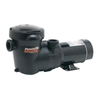
SEAL CHANGE INSTRUCTIONS
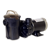
Power Flo™ LX Series with Twist Lock Cord
GENERAL
Exercise extreme care in handling and installing the new seal and ceramic seat assembly.
The lapped and polished surfaces may easily be damaged by dirt or scratching.
For safety, all service must be performed with all power shut off.
Remove pump and motor assembly from piping
system.
Remove pump housing cover (with strainer
attached) by removing the eight (8) housing bolts
and nuts which fasten housing cover to pump
housing. The impeller is now exposed.
To remove impeller, insert screwdriver in slot at
end of motor.* Hold screwdriver so as to keep
shaft from turning, and rotate the impeller in a
counterclockwise direction. The spring portion of
the seal assembly is now exposed.
Note carefully the position of the spring seal and
pull it off the impeller.
To remove the stationary (ceramic seat) part of
the seal assembly:
a. Loosen the four (4) motor securing bolts and
disengage the motor from the pump housing.
b. With motor removed, press the clear plastic
and ceramic seat assembly out of the pump
housing recess. If tight, tap lightly from the
“motor” side.
Clean and lubricate the impeller hub shaft and
pump housing seal recess with a dilute solution
of non-granulated liquid-type soap. The use of
petroleum or silicone lubricants can contribute to
seal leakage.
Press the new spring portion of the assembly
onto the impeller, black polished surface facing
away from the impeller.
Carefully press ceramic seat, with O-ring, into
clear plastic seat retainer—polished surface
facing out. Be sure O-ring is in place on cut ridge
of clear plastic retainer. Press plastic retainer,
with ceramic seat inside, into recess of pump
housing—O-ring end first. Replace the assembly
firmly and evenly.
Carefully insert the motor shaft through the seat
assembly, and secure motor to pump housing
with four (4) motor securing bolts. (Be sure motor
base is positioned properly.)
Screw the impeller, with spring seal, onto the
motor shaft, hand tight, by turning clockwise.
Clean fiber gasket (replace if necessary) and
fasten housing cover to pump housing with
eight (8) bolts and nuts. Tighten bolts and nuts
alternately and evenly.
Reconnect pump to piping system. Be sure to fill
strainer with water before restarting.
1.
2.
3.
4.
5.
6.
7.
8.
9.
10.
11.
12.
* For A.O. Smith Canopy Style Motors: Remove motor end cover and
carefully
apply wrench to flat on motor shaft to hold shaft from turning.
ELECTRICAL GUIDE — 60 CYCLE MOTORS — SINGLE PHASE
VOLTS
MOTOR CIRCUIT BREAKER
RATINGS - AMPS
BRANCH FUSETRON
RATINGS - AMPS
RECOMMENDED
WIRE SIZE
0-50’
KW
HP
#14
#12
#12
15
20
20
15
20
20
115
115
115
3/4
1
1-1/2
.55
.75
1.1
A separate electrical circuit, utilizing a rating as above, is recommended.
 Loading...