Do you have a question about the Hayward TriStar VS Series and is the answer not in the manual?
Read and follow all instructions in the owner's manual and on the equipment for safe operation.
Ensure proper electrical wiring, grounding, and bonding for safe operation and to prevent shock.
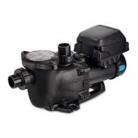
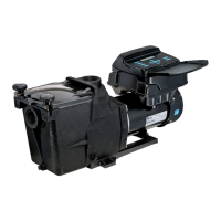
Details on the SP3200VSP model, its stand-alone capabilities, and lack of controller communication.
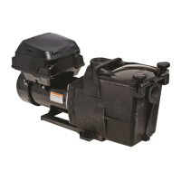
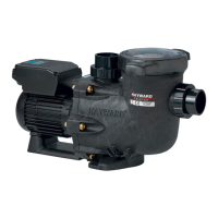
Information on the SP3200VSPND model, its compatibility with automation systems, and control interface.
Guidance for proper pipe and equipment sizing when installing on a new pool.
Ensuring maximum flow does not exceed pipe and equipment capacity in existing pools.
Step-by-step guide to removing and disconnecting the control interface for electrical installation.
Procedure for removing the wiring compartment cover for SP3200VSPND electrical installation.
Details on wiring plugs for wall-mounted interface and controller connections for different models.
Information on incoming line voltage connections, ground wire terminal, and bonding lug.
Explanation of Dip Switches for pump address on SP3200VSPND models.
Guide to removing and repositioning the interface assembly for optimal placement.
Instructions for using the wall mount kit to remotely mount the interface assembly.
Procedure for wiring the pump to Hayward/Goldline control systems for data communication.
List of software versions required for the TriStar VSP SP3200VSPND to operate with controllers.
Guide to configuring the pump address using the SW200 DIP switch settings.
Diagram showing port locations on Jandy AquaLink for valve actuators and relay connections.
Distinction between AC valve actuator ports and DC relay ports, noting which are used.
Instructions for using the GLX-ACT-CONN pigtail for actuator connections to the AquaLink.
Diagram showing how to connect incoming power to the unit via L1 and L2 terminals.
Guidance on using existing ports for multiple actuators when new ports are unavailable.
Wiring instructions for connecting actuators to Speed Step 1, 2, or 3 as needed.
Procedure for connecting pump power (230 VAC) to the Filter Pump Relay.
Connecting auxiliary relays for control signals from third-party systems.
Wiring DC voltage from RS485 to the 'line in' contacts of auxiliary relays.
Connecting the COM terminal on RS485 to the ICOM terminal on the pump interface.
How the number of auxiliary relays dictates the available speeds (2, 4, or 8 speeds).
Table showing specific STEP 1, 2, 3 status for each speed setting (1-8).
Instructions for connecting a remote stop switch to the OVRD and ICOM terminals on the pump.
Overview of preset speed buttons and menu navigation buttons for programming.
Explanation of Stop/Resume, Quick Clean buttons, and Check System/Timers Active LEDs.
Steps to unlock and enter the Configuration Menu by pressing specific buttons.
Guidance on using the '>' button to enter menus and +/- buttons to adjust parameters.
Procedure for setting the current day, hour, minute, and AM/PM in the configuration menu.
Choosing between RPM or percentage of full speed as the speed indicator.
Configuring the maximum speed limit for the pump, from 600-3450 RPM or 17-100%.
Configuring the minimum speed limit for the pump, from 600-3450 RPM.
Adjusting the prime duration period in 30-second intervals, from 15 minutes to zero.
Choosing between Stand Alone (default) or Relay Control mode for pump operation.
Enabling/disabling low temperature operation and setting the activation temperature for drive protection.
Option to reset all parameters to factory settings or skip the reset.
Transitioning to timer programming mode for setting or changing time clock perimeters.
How to access the Timers Menu to begin setting up timer schedules.
Information on Timer 1's factory default settings for RPM, days, and times.
Procedure to modify timer settings or navigate to the next timer.
How to rename timers and adjust speed settings for each timer.
How to change the start and stop times for a specific timer.
Choosing the active days for a timer: individual day, 7-day, or 5-day schedule.
Steps to enter the Speeds Menu to configure individual speed settings.
Applying names to speeds and setting their duration from 30 minutes to 12 hours.
Configuring the speed for each setting from 600 RPM (17%) to 3450 RPM (100%).
How pressing speed buttons selects pre-set speeds and durations, and how +/- adjust speed.
Explanation of Stop/Resume and Quick Clean button functions during operation.
Illustrates a possible stand-alone operating scenario with timer priority explained.
Steps to access the diagnostic screen for viewing pump performance and troubleshooting information.
Overview of real-time displays including firmware revisions, serial number, power, and temperature.
How to access and view the event log for past errors and trip conditions.
Indicates internal overheating. Check motor airflow path and for blockages.
Indicates a problem with the motor drive processor, possibly requiring replacement.
Indicates excessive motor current draw. Check impeller, diffuser, and seals.
Indicates a stuck interface button, potentially requiring interface replacement or unsticking.
Low or high DC bus voltage indicates issues with incoming line voltage.
Indicates an open motor phase, possibly requiring motor replacement.
Addresses interference issues when connected to GL/Hayward controls, causing 'Pool bridge comm'.
Indicates communication problems or damaged/corrupted drive memory, requiring replacement.
Errors due to corrupted drive software or inability to start the motor.
If the breaker trips, check input wiring and breaker; replace drive and motor if persistent.
| Model | TriStar VS Series |
|---|---|
| Type | Variable Speed Pump |
| Voltage | 230V |
| Energy Efficiency | Energy Star Certified |
| Control | Digital |
| Motor Type | Permanent Magnet |
| Controller | Integrated |
| Wet End Material | Thermoplastic |