
A
Autumn CollinsAug 22, 2025
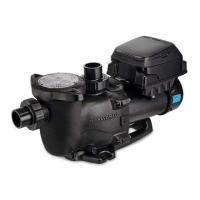
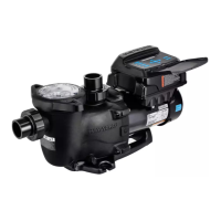
How to fix low flow in my Hayward MaxFlo VS 500?
- CcourtneydunnAug 22, 2025
If your Hayward Swimming Pool Pump has low flow, a clogged or restricted strainer or suction line could be the cause. Correct the piping size for undersized pool piping. Check for a plugged or restricted discharge line of filter, or a valve partially closed. Backwash as per manufacturer’s instructions. Re-tighten the suction and discharge connections using PTFE tape. Inspect other plumbing connections, and tighten as required. A plugged, restricted, or damaged impeller may be the cause, so replace the impeller including a new seal assembly.