3
Salt Level
Use the chart on page 4 to determine how much salt in pounds or (Kgs) need to be
added to reach the recommended levels. Use the equations below (measurements are
in feet/gallons and meters/liters) if pool size is unknown.
The ideal salt level is between 2700-3400 ppm (parts per million) with 3200 ppm
being optimal. If the level is low, determine the number of gallons in the pool and
add salt according to the chart on page 4. A low salt level will reduce the efficiency
of the SwimPure Plus and result in low chlorine production. A high salt level can
cause the SwimPure Plus to shutdown and may begin to give a salty taste to your
pool (generally, the salt will begin to be tasted at a level of about 3500-4000 ppm). The
salt in your pool/spa is constantly recycled and the loss of salt throughout the
swimming season should be small. This loss is due primarily to the addition of water
because of splashing, backwashing, or draining (because of rain). Salt is not lost due
to evaporation.
Type of Salt to Use
It is important to use only sodium chloride (NaCl) salt that is greater than 99% pure.
This is common food quality or water softener salt and is usually available in 40-80 lb.
bags labeled "Coarse Solar Salt". It is also acceptable to use water conditioning salt
pellets, however, it will take longer for them to dissolve. Do not use rock salt, salt with
yellow prussiate of soda, salt with anti-caking additives, or iodized salt.
How to Add or Remove Salt
For new plaster pools, wait 10-14 days before adding salt to allow the plaster to cure.
Turn the circulating pump on and add salt directly into the pool. Brush the salt
around to speed up the dissolving process--do not allow salt to pile up on the bottom
of the pool. Run the filter pump for 24 hours with the suction coming from the main
drain (use pool vac if there is no main drain) to allow the salt to evenly disperse
throughout the pool. The salt display may take 24 hours to respond to the change in
salt concentration.
The only way to lower the salt concentration is to partially drain the pool and refill
with fresh water.
Always check stabilizer (cyanuric acid), when checking salt. These levels will most
likely decline together. Use the chart on page 5 to determine how much stabilizer must
be added to raise the level to 80 ppm.
12
Gallons
Liters
(pool size in feet)
(pool size in meters)
Rectangular
Round
Oval
Diameter x Diameter x
Average Depth x 5.9
Length x Width x
Average Depth x 6.7
Length x Width x
Average Depth x 7.5
Diameter x Diameter x
Average Depth x 785
Length x Width x
Average Depth x 893
Length x Width x
Average Depth x 1000
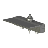
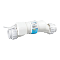
Flow switch connector
Bonding lug to
pool bonding system
Cutout for
cell cable
Wiring
Power must be shut off at the circuit breaker before performing any wiring. Be sure to
follow Local and NEC electrical codes. To provide safe operation, the SwimPure Plus
must be properly grounded and bonded.
Input Power For stand alone operation:
Wire the SwimPure Plus to the LOAD SIDE of the filter pump timer. It is very important
that the SwimPure Plus is powered only when the pump is running.
Refer to the wiring label on the SwimPure Plus as well as the diagram below to determine
correct wiring connections. The SwimPure Plus is shipped from the factory with the
configuration jumpers in 240VAC position. If using 120VAC, move the jumpers as
shown below. For Canadian models, the SwimPure Plus shall be connected to a circuit
protected by a class A ground fault interrupter. Be sure to connect the ground wire to
the green ground screw terminal located on the bottom of the enclosure.
Bonding:
A lug used for bonding is attached to the bottom of the SwimPure Plus enclosure (see
diagram below). The SwimPure Plus must be bonded with an 8 AWG copper wire (6
AWG Canada) to the pool bonding system.
Electrolytic Cell and Flow Switch:
The electrolytic cell and flow switch cables are terminated with connectors which plug
into the SwimPure Plus, for easy attachment and removal. The door of the SwimPure
Plus must be open to access the cell cable connector. The flow switch plugs into a
connector (similar to a telephone jack) located outside, on the bottom of the enclosure.
Refer to the diagram below for the location of these connections.
SUBPANEL
TIMECLOCK
SWIMPURE
PLUS
SWIMPURE
PLUS
PCB
PCB
BONDING
LUG
BONDING
LOOP
PUMP
LINE LOAD
GROUND
GND
GND
IMPORTANT:
MOVE JUMPERS
TO POSITIONS SHOWN
TYPICAL 240 VAC WIRING
120 VAC
Note: Wire the pump directly to the timeclock--do not use the SwimPure Plus as a junction box.
 Loading...