Chapter 3 – Characteristics
15Sound Calibrator Type 4231
User Manual
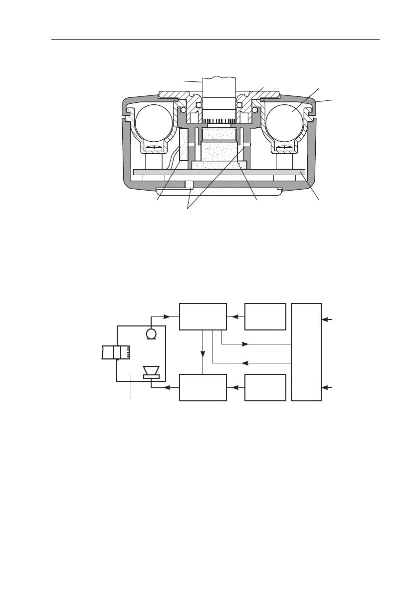
Fig.3.3 Cross-section of the calibrator
Fig.3.4 shows a block diagram that illustrates how the calibrator’s
electronic circuit works. The main components of the diagram are
described in the following sections.
Fig.3.4 Block diagram illustrating the principle of the calibrator’s operation
3.8.1 Feed-back Circuit
The signal from the microphone is fed to the feed-back circuit. The
feed-back circuit contains:
• a band-pass filter
• a temperature compensation circuit
•a detector
930129/1
Reference Microphone
Loudspeaker
Pressure Equalizaon Channels
Circuit Board
Baery
Lid
Microphone to be calibrated
1/2" Adapter
930192/1
Feed-back
Circuit
Variable
Amplitude
Sine Generator
Frequency
Reference
SPL
Reference
Control
Circuit
+20 dB
On/Off
Coupler
Microphone
to be
calibrated
Gain
Overload