Do you have a question about the HBM WTX120 and is the answer not in the manual?
Defines the intended use and limitations of the device.
Specifies environmental requirements for safe operation.
Defines the qualifications required for operating and maintaining the device.
Outlines general safety practices during operation and maintenance.
Details extra safety measures for hazardous environments or potential risks.
Highlights potential hazards from incorrect installation or operation.
Explains the symbol indicating the required supply voltage range.
Guarantees product compliance with relevant EC directives.
Instructions for proper disposal of old electrical equipment.
Identifies symbols used for important instructions, warnings, and emphasis.
Lists key features like ports, enclosure, and load cell terminals.
Details available industrial interface options like PROFINET, EtherNet/IP, Profibus DP.
Lists optional features such as analog output and additional digital I/O.
Details terminal assignments for load cells, supply voltage, digital I/O, and serial interfaces.
Provides guidelines on operating temperature, humidity, and installation location.
Explains how to connect the device to the power supply terminals.
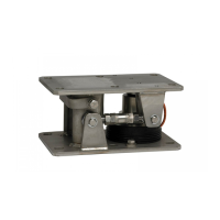
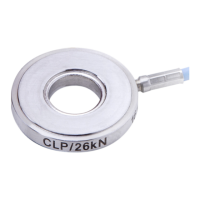
Details specifications for connecting analog strain gage sensors.
Explains configurations for digital inputs and outputs.
Explains how to connect the 15-bit analog output for gross or net weights.
Details the connection of RS232 or RS485 serial ports.
Explains how to connect the device to a PROFINET network using RJ45 sockets.
Explains the meaning of system and bus failure status LEDs for PROFINET.
Details how the weighing terminal works as a PROFINET I/O device and parameter settings.
Explains how to connect the device using the Profibus DP interface.
Describes the WTX120's role as a Profibus-DP slave and address setting.
Explains connecting the device to an Ethernet/IP network using RJ45 sockets.
Explains the meaning of system and bus failure status LEDs for EtherNet/IP.
Details how the WTX120 functions as an EtherNet/IP adapter and parameter settings.
Describes the location and connection requirements for the Ethernet port.
Explains the usage of the USB port for storage devices or keyboards.
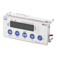
Details how to connect an optional external display.
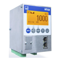
Describes the WTX120 display layout and key functions.
Explains the operator control sequence using user guidance texts and corresponding entries.
Details how to enter character strings, such as FTP passwords.
Explains how to enter a sequence of digits.
Explains how to enter digits with decimal places.
Provides information on accessing menu groups and peripheral settings.
Allows setting parameters like language, time zone, date, and time.
Describes the process of calibrating the scale.
Allows configuring scale settings, digital I/O, and analog output.
Selects the connection for the fieldbus, supporting PROFINET, EtherNet/IP, and PROFIBUS DP.
Allows entering IP addresses for remote control of WTX units.
Performs hardware tests on digital and serial interfaces.
Resets Service Mode values and parameters to factory defaults.
Allows configuration of device-specific network settings like IP address, subnet mask, gateway, DNS, and NTP.
Save and restore data sets to a USB stick.
Allows selection of the WTX120 application, Standard or Filler.
Provides adjustable limit switches for monitoring signal sources in different modes.
Configures digital inputs and outputs for Standard and Filler applications.
Resets all settings to factory defaults, followed by an automatic device restart.
Allows adjusting filter settings for optimization.
Adjusts filter size in calibration mode.
Sets the characteristic of the digital filter.
Sets the filter order.
Sets the optimal filter type for the application.
Adjusts the working window of the vibration filter.
Allows viewing and changing date, time, and password during operation.
Accesses menus for product-specific parameters and results.
Selects between upward (filling container) and downward (emptying container) dosing.
Optimizes coarse and fine flow phases by sensor electronics.
Executes re-dosing if measured value is below the lower tolerance limit.
Monitors empty weight, fill flow, overflow, dosing time, and container status.
Controls coarse and fine flow valves via digital outputs in four modes.
Sets the target weight for the dosing process, automatically adjusting other settings.
Describes the upper and lower tolerance limits for the dosing result.
Stores data sets with weighing date and ident number, up to 120,000 entries.
Lists firmware updates, can be viewed but not changed or deleted.
Allows viewing the identification and version number of the legal-for-trade software.
Configures the A/D converter for single, dual, or triple range scales.
Sets up a single-range scale with two or three different weighing ranges or intervals.
Sets parameters to adapt the A/D converter to the weighing environment.
Sets the calibration location based on geo value for factory pre-calibration.
Specifies resolution and adaptation parameters for legally verified scales.
Selects parameter groups for calibration settings.
Sets weighing ranges, intervals, and unit of measurement symbol.
Performs calibration without weights if load cell sensitivity is known.
Redefines the zero point of the scale, necessary after removing auxiliary frames.
Sets parameters to adapt the A/D converter to the weighing environment.
Displays the weight value in 10 times higher resolution.
Resets A/D converter parameters to default values, requiring recalibration.
Verifies scale parameters against verification requirements.
Uses a data set for extended output to a WTX110 as a remote display.
Allows free configuration of data sets using placeholders.
Explains bit address organization and number format for 16-bit data.
Describes the representation of weight values, matching calibration settings.
Provides an overview of data word content for Standard and Filler applications.
Details the input words from WTX120 to PLC for the Standard application.
Details the input words from WTX120 to PLC for the Filler application.
Explains command reception confirmation via handshake.
Details values for net and gross measured values, their update, and status information.
Provides additional error and status information in data word EW4.
Explains how to import data words using the data import command.
Explains how to enter measured values into the legal-for-trade memory.
Allows checking input and output data words during live operation.
Instructions for transporting and storing the weighing terminal.
Recommendations for visual inspection and checking connected cables.
Provides instructions on how to clean the device safely, listing prohibited substances.
Details the procedure for replacing the internal lithium battery.
First step in troubleshooting: check if the power supply is operational.
Ensure all connected cables and peripheral plugs are undamaged and correctly attached.
Verify that connected sensors are in the correct position and functioning.
Details essential information needed for effective troubleshooting.
Accesses the error log from the Calibration/Calibrate Scale 1 menu.
Lists common error messages, possible causes, and remedies.
Explains that the service password grants access to Service Mode.
Explains where and how to enter geo values based on country.
Provides a table to determine corresponding geo values based on latitude and altitude.
| Brand | HBM |
|---|---|
| Model | WTX120 |
| Category | Accessories |
| Language | English |