7/11/2014 Heat & Glo • 7076-250C 5
Curve 100
2
Installation & Assembly
A. Positioning Your Wood Burning Stove
The wood burning stove must be set up so the stove, fl ue
connection, fl ue pipe, and chimney system can be cleaned
and serviced. Consideration should also be made when
locating the appliance in the home due to the supply of
combustion air requirements. Depending on the chosen
installation method, supplied combustion air may be taken
from the outside using the adapters provided, or through
the back of the unit by removing the cover plate on the
inlet hole. (To remove the cover or install the outside air
adapter, remove the back panel. The cover plate is located
near the bottom and retained with four screws.)
Out of the box, the appliance without the additional weight
of the venting system or fuel load weighs nearly 100
kilograms. Make considerations for the weight of the
system when locating the unit in the desired location. If
the load bearing characteristics of the structure are diffi cult
to determine or there is concern that the structure will not
adequately support the system, a distribution plate should
be used. Contact your Curve Wood Stove dealer with
questions.
B. Vertical Venting & Combustion Air
When venting the appliance vertically, follow the venting
manufacturer’s instructions and requirements. Slip the
cover ring down the fl ue and set on top of the appliance.
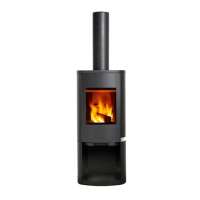
Vertical Venting Options (Fig. 5.1)
Standard 150mm Venting: G, E, B
Coaxial venting: F, E, D, A
(Use the items indicated for your installation. Use the bolts
provided to attach the components in the order shown.)
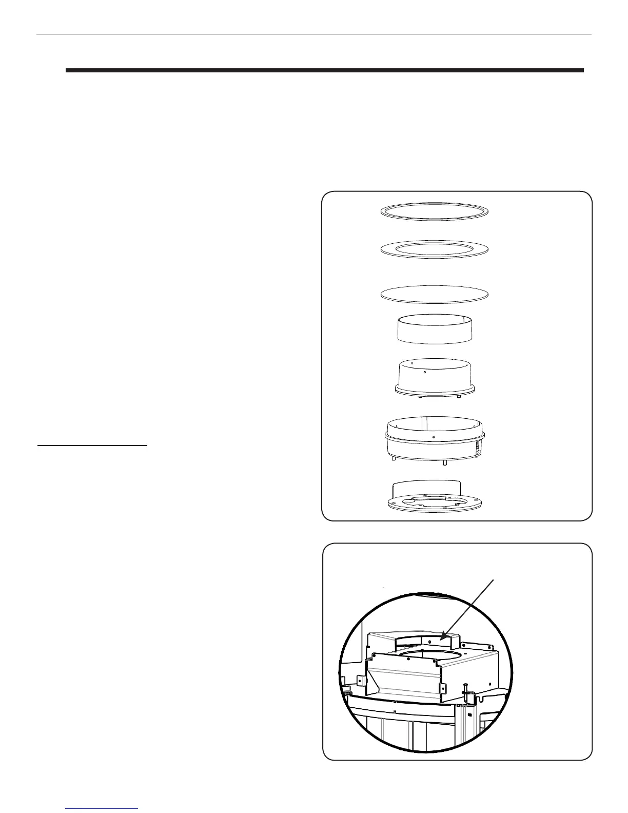
When installing G or F:
• - If installing outside combustion air, turn G or F to
cover the opening at the top of the combustion air
plenum.
• - If using room combustion air, turn G or F to leave the
opening at the top of the combustion air plenum open.
(The outside air connection is located on the lower back
of the stove. The 75mm adapter is included in the
component pack.)
C. Horizontal Venting
When venting the unit horizontally, remove the back panel
of the unit. Next, remove the cast fl ue attachment ring
in the top of the appliance using the four bolts used to
secure it in shipping. Remove the rear cover plate that
can be seen in the back of the unit once the back panel is
removed. Install the rear cover plate over the vertical outlet
hole in the top of the unit using the four bolts that were
used to secure the cover plate when installed on the rear
of the unit. Install the cast fl ue attachment ring on the rear
of appliance using four bolts. Knock out the two panels on
Opening at the top of the
combustion air plenum
the back panel so the fl ue attachment ring can slip through
it. Attach the back panel back onto the appliance using
the same fasteners. Install the venting per the venting
manufactures specifi cations. Place the top cover plate
(item “C” in Fig. 5.1) from the component pack over the
hole in the top of the appliance for a fi nished look.
This unit is suitable for installation in a shared fl ue.
Fig. 5.1
Fig. 5.2
 Loading...