Do you have a question about the Heat Controller B-DVH24SD-1 and is the answer not in the manual?
Instructions to prevent injury to users and property damage.
Warnings regarding installation and operation to prevent hazards.
Lists model numbers for indoor and outdoor units by capacity.
Specifies minimum clearances for indoor and outdoor unit placement.
Lists various features like Auto Restart, Sleep Mode, Turbo Mode, etc.
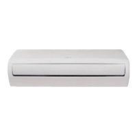
Provides dimensions and specifications for the indoor unit.
Details dimensions and hole specifications for the mounting bracket.
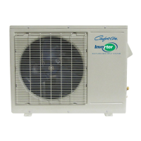
Provides dimensions and specifications for the outdoor unit.
Illustrates the refrigerant flow for cooling-only models.
Illustrates the refrigerant flow for heat pump models.
Shows wiring diagrams for various indoor unit models.
Shows wiring diagrams for various outdoor unit models.
Covers electrical wiring requirements and codes for installation.
Details the required sizes for gas and liquid refrigerant lines.
Specifies maximum allowable lengths and elevation differences for lines.
Instructions for adding refrigerant for field-installed tubing.
Lists abbreviations used for temperature sensors and settings.
Explains the icons and their meanings on the indoor display board.
Details the various protection mechanisms for the compressor and inverter module.
Describes the operation when only the fan is active.
Details compressor and fan operation during cooling.
Details compressor and fan operation during heating.
Explains conditions and process for defrosting the unit.
Describes protection against excessive evaporator coil temperatures.
Explains the automatic mode selection based on temperature difference.
Details the operation and fan speed in dry mode.
Explains how to manually force the unit into specific modes.
Describes the timer functions for controlling unit operation.
Details the sleep mode operation and duration.
Explains how the unit resumes operation after a power failure.
Describes the automatic movement of the front panel.
Details the low-temperature heating feature for frost protection.
Lists error codes displayed on the indoor unit and their meanings.
Provides diagrams of outdoor PCBs and notes on LED indicators.
Diagnoses and provides solutions for EEPROM parameter errors.
Guides troubleshooting for communication errors between units.
Diagnoses and resolves zero crossing detection errors.
Provides steps to diagnose and fix fan speed control issues.
Guides troubleshooting for temperature sensor open or short circuits.
Diagnoses and resolves refrigerant leakage or blockage issues.
Diagnoses IPM malfunction or IGBT over-current protection errors.
Diagnoses and resolves compressor top high-temperature protection issues.
Diagnoses inverter compressor drive errors.
Provides pressure readings for cooling mode based on temperatures.
Provides pressure readings for heating mode based on temperatures.
| Phase | 1 |
|---|---|
| Refrigerant | R410A |
| Cooling Capacity | 24000 BTU |
| HSPF | 9.0 |
| Voltage | 208/230V |
| Heating Capacity | 24000 BTU |
| Operating Temperature (Cooling) | 5°C to 43°C |