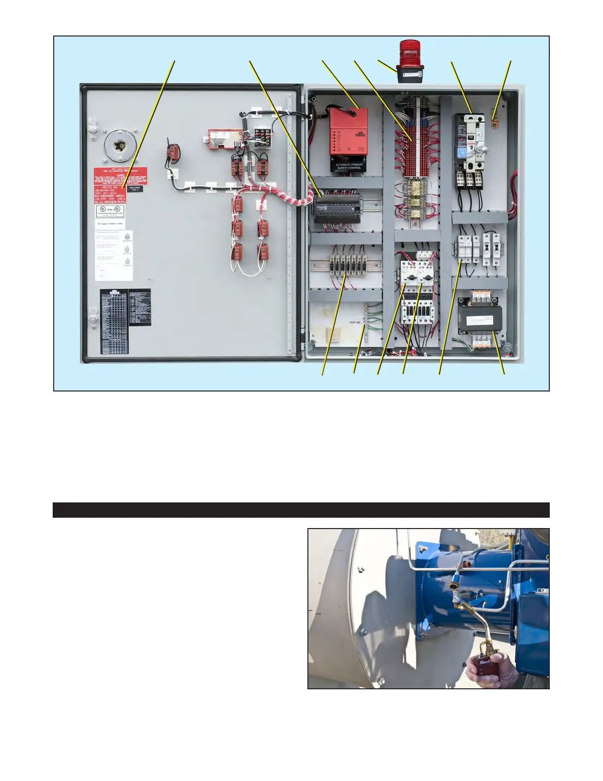
Figure 6. Flame scanner.
4. Open the top of the chamber where the
switches are installed.
5. Insert the hooked end of the wire into the
channel and grab onto the float of a switch.
6. Move the float up and down while observing
the light on the PLC. The light should go on
and off in response to float movement.
7. Repeat steps 5 and 6 for each of the remain-
ing switches.
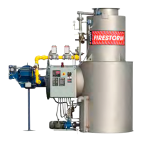
Figure 5. Components inside the control panel.
Publication 1-10-218
Page 6
A B C D
E F
H
G
IJKL
M
A. Voltage label
B. PLC (Programmable Logic Controller)
C. Fireye burner management control YB110
D. Terminals and relays
E. Alarm strobe light
F. Main disconnect breaker
G. Grounding lug
H. Control transformer
I. Circuit breakers and fuse blocks
J. Blower motor controller
K. Water pump motor controller
L. Equipment grounding strip
M. Fused terminals