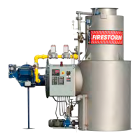
Figure 4. Components outside the control panel.
One way to protect it from freezing is to drain all
water from the heater shell, float chamber, piping,
pump and strainer. All of these have drain plugs
except for piping, which may require loosen-
ing connections to allow drainage where water is
trapped.
As an alternative to draining water from the pip-
ing you may want to install heat tracing around the
piping.
CHECKING WATER LEVEL SWITCHES
Check water level switches (I, J, K, L, Fig. 3) if
you encounter any of the following symptoms:
• Pump won’t run
• Tank overflows
• Outlet water valve is inoperative
• Pump cycles on/off
To check the switches proceed as follows:
1. Obtain a scrap piece of stiff wire (or a coat
hanger) about 3 feet long. Bend one end of
the wire to form a small hook.
2. Open the control panel so you can observe
the lights on the PLC (B, Fig. 5).
3. Turn on the electrical power using the main
disconnect breaker (F, Fig. 5) inside the
panel.
Note: Earlier panel marking FIREYE FLAME MONITOR is now BURNER DISPLAY
Publication 1-10-218
Page 5