EasyManua.ls Logo

Heathkit HR-10B - Introduction; Circuit Description; RF Amplifier - Mixer Oscillator; IF Amplifier

Heathkit HR-10B
53 pages
To Next Page IconTo Next Page
To Previous Page IconTo Previous Page
Loading...
Page
8
INTRODUCTION
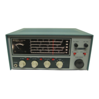
Your HEATHKIT Model
HR-10B
Basic
Amateur
Band
Receiver
is
designed
for
use
as
a
high-
performance
economical
station
receiver,
Fre-
quency
coverage
of the
Receiver
includes
the
amateur
bands,
80
through
10
meters,
only,
Each
band
is
separately
calibrated
on a
large
easy-
to-
read
slide-rule
dial,
The
dial
is
illuminated
and
provides
approximately
6
inches
of
band-
spread
for
each
band,
The
Receiver
features
a:
signal
strength
"S"
meter,
a
front
panel
dial
calibration
control
that
operates
in
conjunction with
the
100
kc
crystal
calibrator
provisions,
a
tuned
RF
ampli-
fier
stage,
a
crystal
filter,
an
automatic
noise
limiter
circuit,
plus
many
other
features
de-
sirable
on an
Amateur
Receiver,
The
low-
silhouette
styling
and
the
green-gray
color
combination
will
prove
an
attractive
addition
to
any
surroundings.
Refer
to
the
"Kit
Builders
Guide"
for
complete
information
on unpacking,
parts
identification,
tools,
wiring,
soldering,
and
step-by-step
as-
sembly
procedures,
CIRCUIT
DESCRIPTION
ANTENNA
50-75
n
VI
66Z6
RF
AMP.
1/2
6EA8
MIXER
V2B
1/2
6EA8
LOCAL
osc.
1/2
LATTICE
XTAL
FILTER
6.3
V
AC
To
assist
you in
understanding
the
following
Circuit
Descripnon,
we
suggest
that
you
refer
frequently
to
the
Schematic
and Block
Dia-
grams.
As
the
BAND
switch
is
quite complex,
the
circuit
will
be
discussed
with
the
switch
in the 80
meter
position.
RF
AMPLIFIER-
MIXER OSCILLATOR
Assuming
that
the
BAND
switch
is
ill
the
80
meter
position,
the
signal
from
the
antenna
is
applied
through
coil
L1,
through
the
BAND
switch, and
through
capacitor
C7
and
resistorR1
to
the
grid
of
the
RF
amplifier
tube, V1,
V1
amplifies
the
RF
signal
which
is
then
applied
through
capacitor
C18 and
resistor
R10
to
the
grid
in
the
pentode
section
of
tube
V2.
Tube
V2
is
a combination
mixer
and
oscillator,
This
tube
heterodynes
or
mixes
the
incoming
signal
frequency
with
the
oscillator
frequency
to
obtain a
difference
frequency
of
1681
kc,
The
positien
of
the
BAND
switch
determines
which
V3
68A6
1ST
IF
AMP,
210
voc
125
voc
110
VDC
I/<?6EAS
2ND
IF
AMP.
"'
1/2
6EA8
OFO
vs
6BJ7
DET.
AVC
ANC
VOA
1/2
6EBB
1ST
AUDIO
VOB
1/2
6EBB
AUDIO
OUTPUT
'"
SPEAK(R
soon
~HONES
coils
and
capacitors
are
used
in
conjunction
with
V2B
in
the
oscillator
circuit.
These
coils
and
capacitors,
including
the
MAIN
TUNING
ca-
pacitor,
are
used
to
set
the
oscillator
frequency
1681 kc
higher
than
the
desired
radio
station
fre-
quency.
The
difference
frequency
of
1681
kc
is
called
the
intermedia~e
frequency
or
IF
signal.
'
When the
Receiver
is
~sed
on
10
and15
meters,
the
oscillator
operates
at
1/2
the
incoming
frequency
plus
the
intermediate
trequency,
The
difference
frequency,
or
IF,
is
obtained
by
beating
the
second
harmonic
of
the
oscillator
frequency
against
the
incoming
signal,
IF AMPLIFIER
From
the
plate
of V2A;
the
signal
is
coupled
through
IF
transformer
T1
to
the
grid
of
the
first
IF
amplifier
tube,
V3,
A
crystal
filter
is
used
in
the
secondary
cir-
cuit
of
the
IF
transformer
to
provide
a
nar-
row
bandpass
for
suppression
of unwanted
adjacent
signals,
This
provides
the
Receiver

Related product manuals