Plug the line cord into
an
AC
outlet.
Turn the
POWER switch ON.
Adjust
the
FEEDBACK control until the panel meter
reads between
6 and 8 on
the
0-10 scale.
Set
the
external voltmeter
to
read 10 volts AC.
Connect the external voltmeter common lead to the
black sine wave
output
binding post. Connect the other
voltmeter lead
to
the red sine wave
output
binding
post.
( ) Adjust
the
METER
CAL
control until the panel meter
reads
the
same,
on
the 0-10 scale,
as
the
voltmeter.
( )
Disconnect the external voltmeter.
Set
the
oscilloscope to display a 1000
Hz
waveform at
an amplitude
of
10 volts.
Connect
the
oscilloscope
to
the
sine wave
output
binding posts.
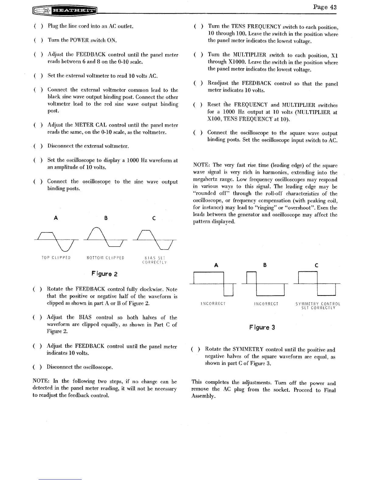
A
B
c
C\
v
TOP
CLIPPED
BOTTO'v1
ell
P?ED I
AS
SE;
REef
Figure 2
( ) Rotate the FEEDBACK control fully clockwise. Note
that
the
positive or negative half
of
the waveform is
clipped as shown in part A or B
of
Figure
2.
( ) Adjust
the
BIAS control
so
both
halves of the
waveform are clipped equally, as shown in
Part C of
Figure
2.
( ) Adjust
the
FEEDBACK control until the panel meter
indicates
10 volts.
( ) Disconnect the oscilloscope.
NOTE: In the following two steps, if
no
change can be
detected in
the
panel meter reading, it will not be necessary
to
readjust
the
feedback control.
Page
43
( ) Turn the TENS FREQUENCY switch
to
each position,
10 through 100. Leave the switch in the position where
the
panel meter indicates the lowest voltage.
( ) Turn
the
MULTIPLIER switch
to
each position,
Xl
through
XIOOO.
Leave the switch in the position where
the panel meter indicates the lowest voltage.
( ) Readjust the FEEDBACK control
so
that the panel
meter indicates 10 volts.
( ) Reset
the
FREQUENCY and MULTIPLIER switches
for a
1000
Hz
output at 10 volts (MULTIPLIER at
XIOO,
TENS FREQUENCY
at
10).
( ) Connect the oscilloscope
to
the
square wave output
binding posts.
Set the oscilloscope input switch
to
AC.
NOTE: The very fast rise time (leading edge)
of
the square
wave signal
is
very rich in harmonics, extending into the
megahertz range. Low frequency oscilloscopes may respond
in various ways
to
this signal. The leading edge may be
"rounded
off"
through the roll-off characteristics
of
the
oscilloscope, or frequency compensation (with peaking coil,
for instance) may lead
to
"ringing" or "overshoot". Even the
leads between the generator and oscilloscope may affect the
pattern displayed.
A B
INCORRECT
INCORRECT
Figure 3
c
SYMMETRY CONTROL
SET
CORRECTLY
( ) Rotate the SYMMETRY control until the positive and
negative halves
of
the square waveform are equal,
as
shown in part C
of
Figure
3.
This completes the adjustments. Turn
off
the power and
remove
the
AC
plug from the socket. Proceed
to
Final
Assembly.