Page
65
DIFFERENTIAL
VOLTAGE
EMITTER
FOLLOWER
ATTENUATOR
AMPLIFIER
AMPLIFIER
POWER
AMPLIFIER
SW
ITCH
~
C
01,
02
r--
03
04,
05
J
NOTCH
I
I
FILTER I
SCHMITT
EMITTER
FOLLOWER
ATTENUATOR
L...-.
TRIGGER
POWER
AMPLIFIER
S
WI
TC
H
~
06,
07
08
ru
POWER
SUPPLY
05,
D6, 010
1---+43
VDC
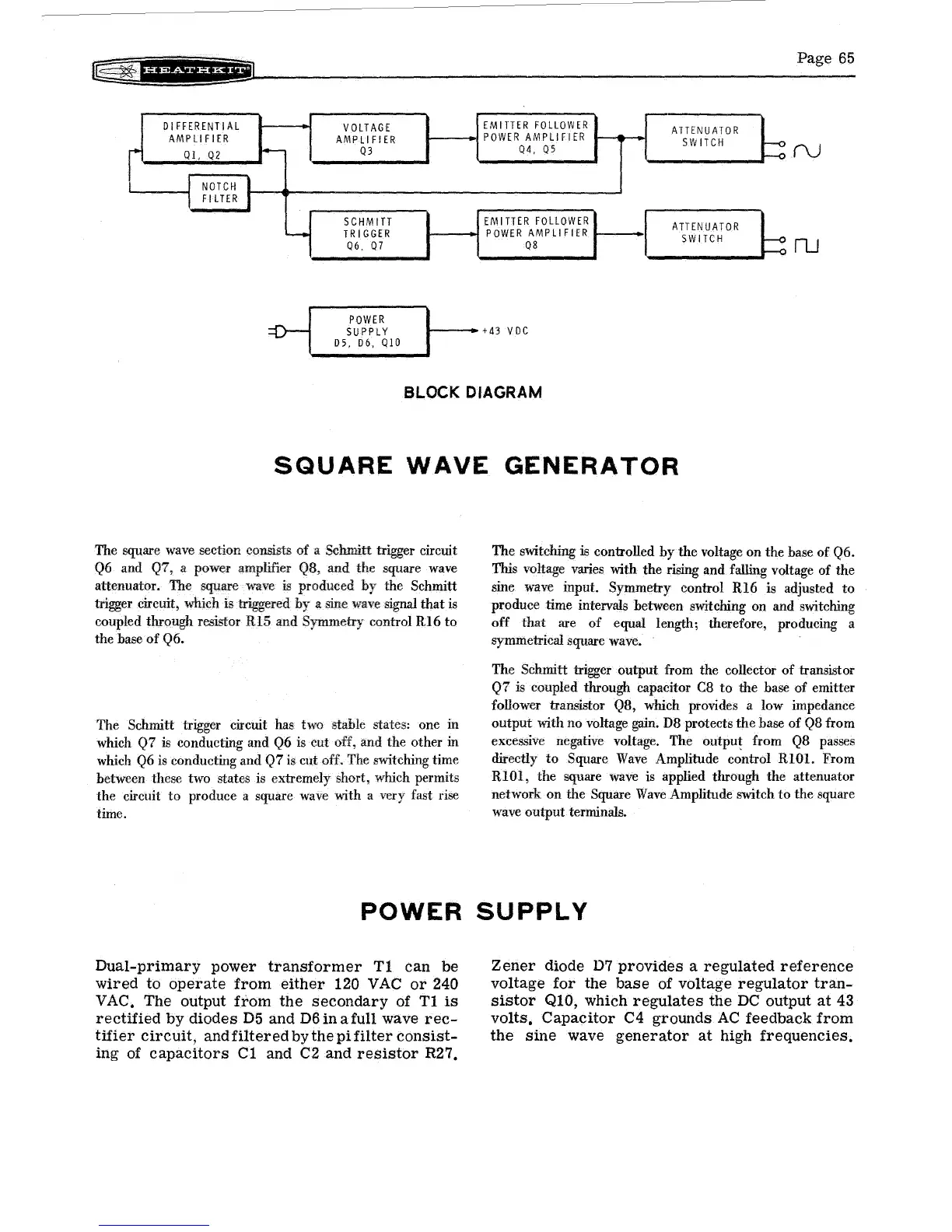
BLOCK DIAGRAM
SQUARE
WAVE
GENERATOR
The square
wave
section consists
of
a Schmitt trigger circuit
Q6
and Q7, a power Q8,
and
the square
wave
attenuator. The square wave
is
produced the Schmitt
trigger circuit, which is triggered a sine
wave
signal
that
is
coupled through resistor
RI5
and Sy-mmetry control
RI6
to
the base
of
Q6.
The
Schmitt trigger circuit has two stable states: one in
which Q7
is
conducting and Q6 is cut off, and the other in
which
Q6
is
conducting and Q7
is
cut off. The switching time
between these two states is extremely short, which permits
the circuit
to
produce a square
wave
with a very fast rise
time.
The switching
is controlled
by
the voltage on the base of Q6.
This voltage varies with the rising and falling voltage of the
sine wave input. Symmetry control
RI6
is adjusted
to
produce time intervals between switching on and switching
off
that
are
of
equal length; therefore, producing a
symmetrical square wave.
The
Schmitt trigger output from the collector of transistor
Q7
is coupled through capacitor
C8
to
the base of emitter
follower transistor Q8, which provides a low impedance
output
with no voltage
gain.
D8 protects the base
of
Q8
from
excessive negative voltage. The
outpu! from
Q8
passes
directly
to
Square
Wave
Amplitude control RIOl. From
RIOl, the square
wave
is
applied through the attenuator
network
on
the Square
Wave
Amplitude switch
to
the square
wave
output terminals.
POWER
SUPPLY
Dual-primary
power
transformer
T1
can
be
wired
to
operate
from
either
120
VAC
or
240
VAC,
The
output
from
the
secondary
of T1
is
rectified
by
diodes
D5
and
D6
in
a full wave
rec-
tifier
circuit,
and
filtered
by
the
pi
filter
consist-
ing
of
capacitors
C1
and C2
and
resistor
R27.
Zener
diode
D7
provides
a
regulated
reference
voltage
for
the
base
of voltage
regulator
tran-
sistor
QI0,
which
regulates
the
DC
output
at
43
volts,
CapaCitor C4
grounds
AC
feedback
from
the
sine
wave
generator
at
high
frequencies,