Page
48
SINE WAVE AMPLITUDE
The
output
of
the
Audio Generator must be properly
terminated
to
obtain accurate meter indications.
To obtain correct meter readings with a high impedance load
(10 Jill or more); set
the
600.Q LOAD switch
to
INT, and set
the
SINE
WAVE
AMPLITUDE switch
to
the nearest full
scale value above the desired output level. Then adjust the
SINE
WAVE
AMPLITUDE
controlto
give
the desired
output
on the proper meter scale. EXAMPLE: For
an
output voltage
of
7.3 volts, set
the
SINE
WAVE
AMPLITUDE switch
to
10
volts. Then
turn
the
SINE
WAVE
AMPLITUDE control
to
give a 7.3 reading on
the
0-10 scale of the meter. EXAMPLE:
For
an
output
of
.025 volt, set the SINE
WAVE
AMPLITUDE switch
to
.03 volt. Then
turn
the
SINE
WAVE
AMPLITUDE control
to
give
a 2.5 reading on the 0-3 meter
scale.
To obtain correct meter readings with an external
600
.Q
load
(1
volt maximum
output
signal level): set the LOAD switch
to
EXT and proceed
as
before.
SQUARE WAVE AMPLITUDE
To select a square wave
output
level, set the COARSE
SQUARE
WAVE
AMPLITUDE switch
to
the
lowest range
that
includes the desired voltage. Then adjust the FINE
SQUARE
WAVE
AMPLITUDE control until the required
voltage is produced. The front panel voltage ranges
(.lv,
lv,
and lOv) are for loads
of
2000
.Q
impedance or more. Output
level may be measured with a high impedance
AC
voltmeter
or with an oscilloscope. Remember
that
a square
wave
is
measured in peak-to-peak volts and that most
AC
voltmeters
indicate rms volts.
CAUTION: The square wave generator
output
is DC-coupled
to
avoid poor low frequency response (see "Square
Wave
Testing" on Page 52). The
output
is a
DC
signal
that
varies
from zero
to
some positive value when measured
at
the
r------,
>---:--1
---.
I
!
}p70\2
\
I G -18
600
\2
I G -18
600
\2
I I
I
:
I I
I
1-
300\2 I
300<;)
I I
LOAD
I I •
I I
I.
______
J
r-------,
I
I
,
I
I
I
I
560
\2
I
I
I
I
I
I
750.
72\2
I
LOAD
I
I
I
L
______
..I
Figure
5
output
terminals.
Do
not
connect this generator
output
into
DC
circuitry without using capacitive coupling. (Observe
proper capacitor polarity.)
Do
not
short the
output
terminals
at
maximum
(1O.0V')
output.
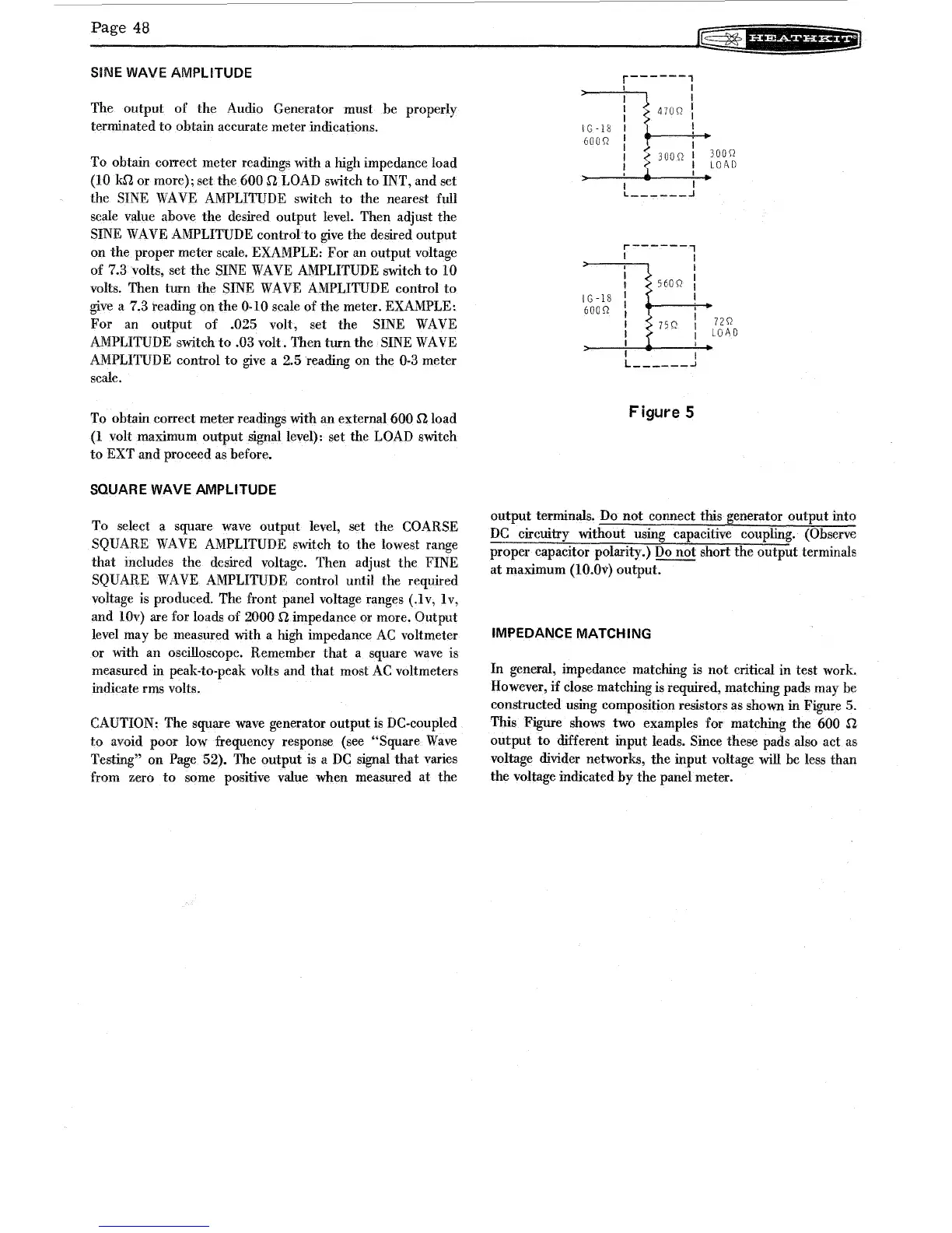
IMPEDANCE MATCHING
In general, impedance matching is
not
critical in test work.
However,
if
close matching is required, matching pads may be
constructed using composition resistors as shown in Figure 5.
This Figure shows two examples for matching
the
600
.Q
output
to
different input leads. Since these pads also act as
voltage divider networks,
the
input voltage will be less than
the
voltage indicated
by
the
panel meter.