- 12 -
PICTORIAL 6-5
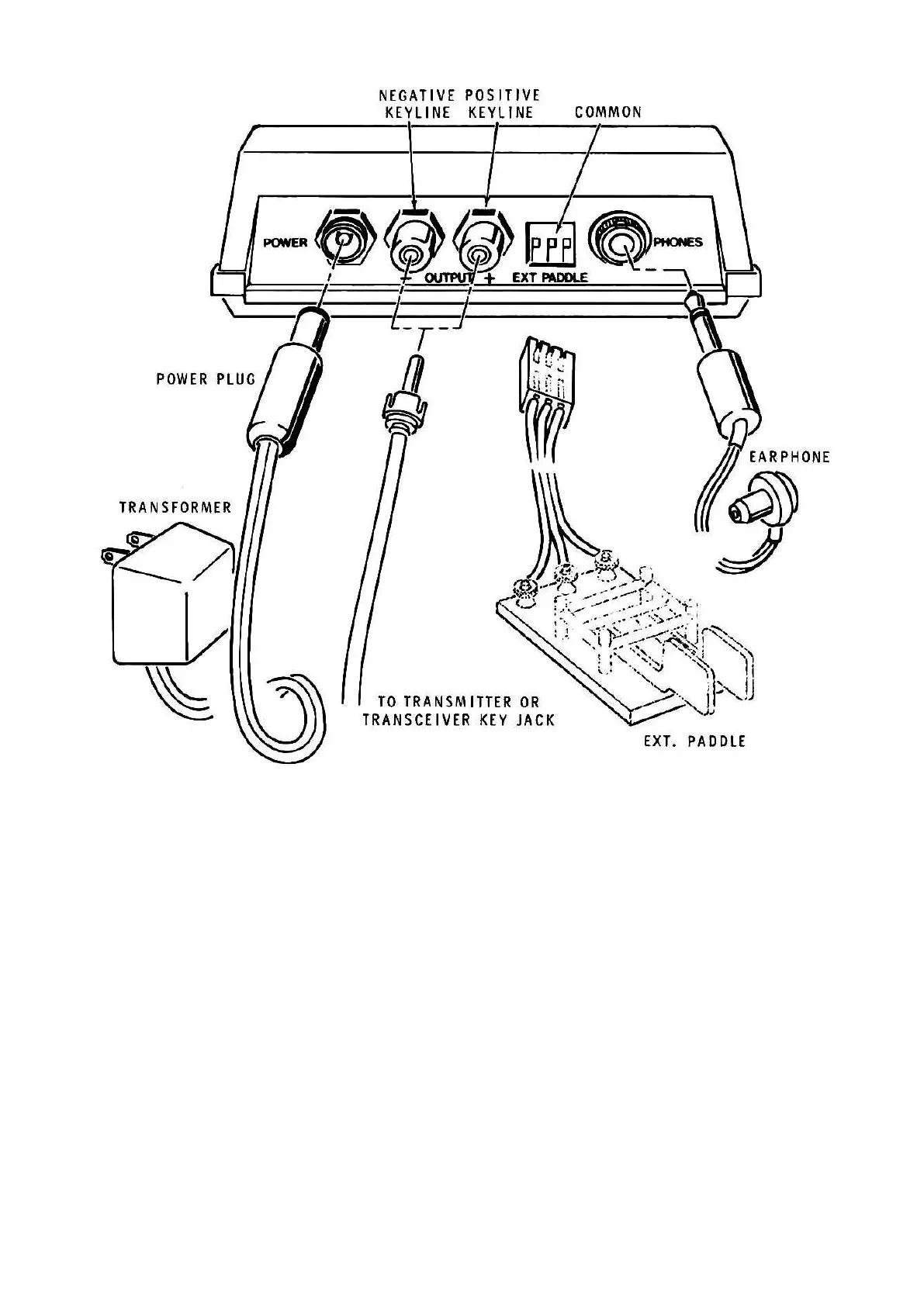
TRANSMITTER AND EXTERNAL KEY CONNECTIONS
Two jacks are provided on the rear panel of the keyer; one keys the positive (+) keylines to
ground and the other keys the negative (–) keylines to ground. If you are not sure which jack to
use for a particular transmitter, you may examine the transmitter schematic, or you may simply try
one jack or the other. If you select the wrong jack, the protective diode across the jack inside the
keyer will continuously key the transmitter. NOTE: Use coaxial cable between the keyer and trans-
mitter.
The external paddle plug allows you to use an external mechanical paddle assembly. Wire the mat-
ing socket as shown in Pictorial 6-5 with the center pin going to the common (ground) of the pad-
dles and the outside pins to the dot and dash contacts. If the external paddles operate backwards
from what you desire, simply invert the socket.
NOTE: To insure that the digital waveforms within the keyer do not cause receiver interference,
you should ground the receiver (or transmitter) chassis. Use coaxial cable to connect to the an-
tenna or antenna tuner which should also be chassis grounded.