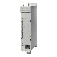
TNC 151 B / TNC 155 B / TNC 151 BR / TNC 155 BR Connections and PLC-allocation
Control
PLC-
TNC
allo-
151 Bl
User
cation
155 B
lz
--
-u
--
-u
--
--
e
E
--
--
--
--
--
*-
‘-
*-
--
‘-
--
‘-
--
--
----c-
1.
37
-
A0
Al
A2
A3
A4
A5
A6
A7
A8
A9
A10
All
Al2
Al3
Al4
Al5
Al6
Al7
Al8
A19
A20
A21
A22
E23
E22
E21
E20
El9
El8
El7
E8
EO
El
E2
E3
Jl
1
2
3
4
5
6
7
8
9
10
11
12
J2
1
.2
3
4
5
6
7
8
9
10
11
12
J3
1
2
3
4
5
6
7
8
9
10
11
12
J4
1
2
3
4
5
6
7
8
9
10
11
12
J5
1
2
3
4
5
6
7
8
9
10
11
12
J6
XT--
1
E5 2
E6 3
E7 4
E9 5
El0 6
El1 7
El2 8
El3 9
El4 10
CY
zyl
Release
Z
- WI
- Co&r01 in operation
- Control in automatic mode
L Lock for spindle on
- Emergency stop (no output from direct NC-part of machine)
+ 24 V supply
+ 24 V supply
+ 24 V supply
+ 24 V supply
+ 24 V supply
ti M-S-T Code Bit 1
5 M-S-T Code Bit 2
5 M-S-T Code Bit 3
: M-S-T Code Bit 4
= MS-T Code Bit 5
L M-S-T Code Bit 6
; M-S-T Code Bit 7
- M-S-T Code Bit 8
- MO3 Spindle clockwise
z MO4 Spindle counter-clockwise
c MO5 Spindlestop
- MO8 Coolant on
5 MO9 Coolant off
) S-Strobe
= M-Strobe
1
Gating signal
- T-Strobe
Zk
do not assign
- do not assign
5 Housing
- +I- 1
OVf
) Analogue output X
- +/-
- ov
Analogue output Y
= +/-
- ov
J
Analogue output 2
* +I-
- ov
>
Analogue output IV
* +I-
- ov
>
Analogue output spindle
do not assign
= 0 V Return line
q Stop-button
- Start-button
/-
Rapid traverse button
Supervision of contact “Lock for spindle on”
d-
Manual feed (opens position loop)
Feed rate release
Feedback: Auxiliary function completed
- Feedback: Emergency stop test (is directly interrogated by NC-part of control)
2~ Reference end position X
Reference end position Y
4--J-
Reference end position Z
Reference end position IV
A-
Reference pulse suppressor X
-- Reference pulse suppressor Y
- Reference pulse suppressor Z
Reference pulse suppressor IV
- Direction button X+
- Direction button X-
_-----
Direction button Y+
--
Direction button Y-
Direction button Z+
Direction button Z-
/-
Direction button IV+
Direction button IV-
113

 Loading...


