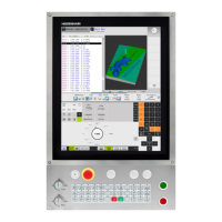
Do you have a question about the HEIDENHAIN TNC 155 W and is the answer not in the manual?
Details incremental linear transducers with 20 µm or 10 µm grating pitch.
Covers outputs for M, S, T functions and strobe/feedback signals.
Explains M-functions operative at block beginning, including coded and decoded types.
Explains function and supervision of the emergency stop circuit.
Describes inputs for reference point detection and pulse suppression.
Parameters for rapid feeds, spindle speeds, axis designation, etc.
Parameters for optimizing trailing error and positioning behavior.
Parameters for activating PLC sections, macros, and user cycles.
Parameters for handwheel sensitivity and touch probe system setup.
A checklist for control adjustment procedures.
Explains axis designation conventions and the right-hand rule for movement direction.
Covers assignment of transducer inputs and axis switchover for axis IV.
Procedure for verifying and correcting axis movement and counting directions.
Process for entering maximum possible traverse options and evaluating axis limits.
Steps for adjusting offsets to optimize machine positioning.
Fine adjustment of trailing error for the linear ramp characteristic.
Procedure for determining machine parameter 54 for acceleration.
Parameter setup prior to adjusting the square root characteristic.
Configuration of acceleration ramp influenced by parameter 64.
Adjusting parameter 53 for deceleration ramp near the nominal position.
Defines ranges for constant position supervision using parameters 56 and 57.
Details how integral factor affects automatic offset adjustment with small position deviations.
Provides an example of a "Bolt hole circle" macro with entry parameters.
Guides on programming customized macros using program numbers and dialogue initiation.
Example of defining a "Bolt hole circle" macro within a machining program.
Lists parameters for activating and optimizing the Vth axis positioning loop.
Lists parameters for setting rapid traverse speeds and manual feed rates.
Shows terminals and PLC allocation for the first PLC board on Q/QR models.
Details terminals and PLC allocation for the second PLC board on Q/QR models.
Shows PLC-board terminals and allocation for standard PLC programs.
| Control Type | CNC |
|---|---|
| Input Method | Keyboard |
| Manual Data Input (MDI) | Yes |
| Data Interface | RS-232 |
| Memory | 64 KB |
| Number of axes | 3 |
| Controlling axes | X, Y, Z |
| Keyboard | Alphanumeric |
| Program Storage | Internal memory and external storage |
| Program Editing | Yes |
| Tool Compensation | Yes |
| Cycle Programming | Yes |


