INSTALLATION INSTRUCTIONS Fan Coil: FMA4X, FMA4P
Specifications subject to change without notice.
496 01 8001 04
3
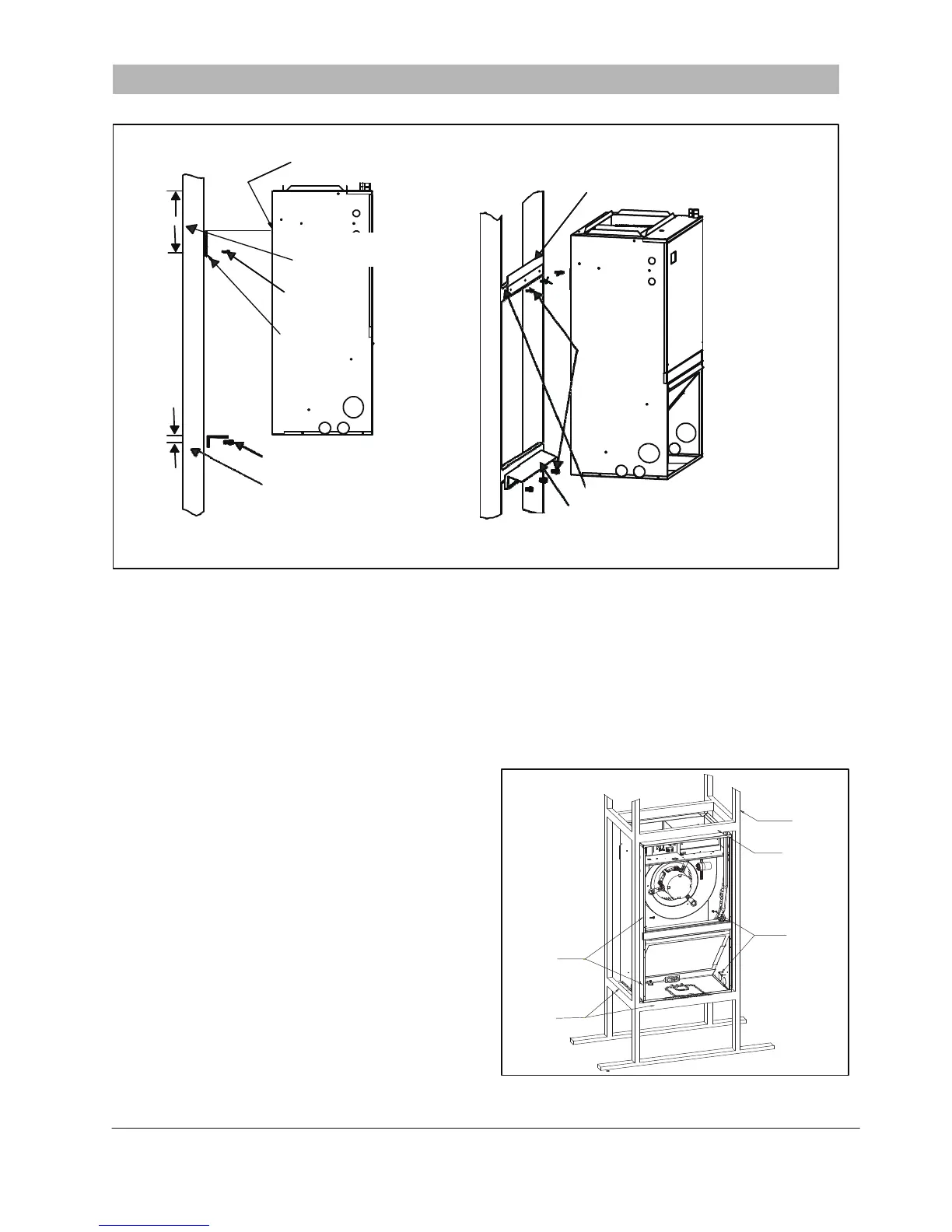
Figure 3
-
Wall Mount Installation
Wall Mount
Frame Mount
L14S011
The fan coil comes standard with a wall mounting bracket
and fan coil mounting bracket. Reference
Figure 3
for more
detail.
1.
Remove the wall mounting bracket from the back of the
unit by removing one screw which attaches the bracket
to the fan coil.
NOTE
: Discard the screw after you have removed the wall
mounting bracket.
2.
Install bracket on the wall by using three wood screws
(not provided) per wall- mount bracket. Make sure the
bracket is level in order to provide proper drainage from
the unit.
NOTE
: Do not attach the wall mounting bracket into
unsupported drywall. Make sure that the wood screws are
going into a structure that can support a minimum load of 150
pounds.
3.
Lift the fan coil above the wall mounting bracket and
attach the unit to the installed bracket. Reference
Figure 3
.
The fan coil comes with eight clearance holes, four on each
side. These holes are used to mount the fan coil inside a
frame structure (see
Figure 4
). When mounting in this
fashion, make sure that the wood screws are mounted from
within the fan coil and not outside of the unit. Installing the
screws from outside of the unit may damage the coil.
After moving unit into place, install refrigerant tubing as
follows:
1.
Route tubing to connection points, taking care not to
block service access.
2.
Remove plugs from liquid and vapor lines.
3.
Braze connections using either silver bearing or
non
-
silver bearing brazing material. Do not use soft
solder (materials which melt below 800°F / 427°C).
Consult local code requirements. Always flow nitrogen
through the system refrigerant lines while brazing.
4.
Pressurize system and leak-test. Repeat procedure
until leak- free.
PROVIDED FAN -COIL
MOUNT BRACKET
PROVIDED WALL
MOUNT BRACKET
WALL BRACKET SCREW HOLES
ARE LOCATED 9” (229 MM) FROM
THE TOP OF THE UNIT
WOOD
SCREWS
PROVIDED
WALL MOUNT
BRACKET
WOOD
SCREWS
WOOD SCREWS
WALL BRACKET SCREW HOLES
ARE LOCATED 1” (25 MM) BELOW
THE BOTTOM OF THE UNIT
SUPPORTING 2” X 4”
(51 X 102 MM) STRUCTURE
WALL MOUNT BRACKET FOR USE
WITH 30 AND 36 SIZE MODELS,
PROVIDED ON THOSE SIZES.
NOTE: Mounting wall and supporting structure must be able to support a minimum of 150 lbs (68 kg).
WALL
STRUCTURE
SUPPORTING
2” X 4”
(51 X 102 MM)
STRUCTURE
STUD
HOLES
WOOD
SCREWS
SUPPORTING
2” X 4”
(51 X 102 MM)
STRUCTURE
Figure 4 - Frame Mount Installation
A13008
NOTE
: FMA4P are shipped with a piston metering device
designed for the most common outdoor unit matches. Refer to
AHRI ratings to check if your combination can use the piston
shipped with the unit or requires an accessory TXV. FMA4X are
provided with a factory installed TXV.