INSTALLATION INSTRUCTIONS Fan Coil: FMA4X, FMA4P
Specifications subject to change without notice.
496 01 8001 04
5
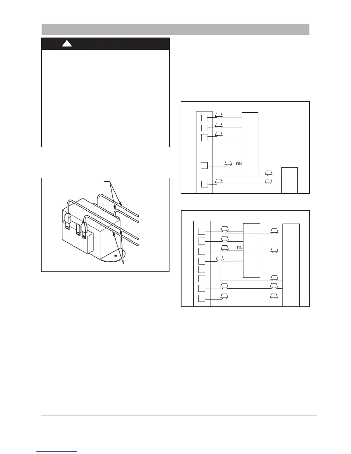
SECONDARY
BLK
YEL
BLK
RED
PRIMARY
to fit the opening. The cut edge of the insulation should
be reinforced with foil tape to prevent fraying. The foil
facing and insulation shall not be removed beyond the
knockout opening size.
4.
Install plastic grommet packed with unit in hole for
low
-
voltage wires.
5.
Connect low
-
voltage leads to thermostat and outdoor
unit. See
Figure 7
and
Figure 8
as well as the outdoor
unit wiring label.
Figure 8
-
Wiring Layout Air Conditioning Unit
(Cooling and 1
-
Stage Heat)
NOTE
: All units are shipped from factory wired for 240VAC
transformer operation. For 208VAC operation, move primary
lead from 240VAC terminal to 208VAC terminal.
Figure 6 Transformer Connections
Figure 8
-
Wiring Layout Heat Pump Unit
(Cooling and 2
-
Stage Heat)
A150158
A13092
See
Figure 7
and
Figure 8
for field low
-
voltage wiring. See
Figure 1
for location of the electrical inlets. For maximum
ampacity and over
-
current protection, see unit
rating plate or
product data sheet.
1.
Provide power supply for unit being installed in
accordance with unit wiring diagram and rating plate.
2.
Connect line
-
voltage leads to the harness pigtail or the
heat
-
kit circuit breaker. Use copper wire only.
Step 6 — Select Proper Blower Speed
A
150159
3.
Use UL listed conduit and conduit connector for
connecting line
-
voltage leads to unit and obtaining
proper ground. If conduit connection uses reducing
washers, a separate ground wire must be used.
G
rounding can also be accomplished by using the
ground lug provided in the control box. Power wiring
may be connected
to either the right or left sides or top
of unit. Knockouts of 7/8” (22 mm) dia. are provided for
connection of power wiring to unit. Some heater sizes
may require a conduit larger than the 7/8” opening; in
this situation the high
-
voltage connection opening
should be enlarged to fit the conduit.
When removing the knockouts for
electrical
connections, an opening in the insulation should be cut
Be
fore operating unit, be sure that the proper blower speed
has been selected. Fan speeds are selected manually.
To change the fan speed on model FMA4P:
Factory default fan speed is
medium
; fan
-
motor red wire
connected to fan relay No. 4.
For
high
speed, connect fan
-
motor black wire to fan relay
No. 4.
For
low
speed, connect fan
-
motor blue wire to fan relay No.
4 and fan
-
motor red wire to fan relay No. 6.
Always connect the unused fan
-
motor
wire to the dummy
terminal block.
When selecting the proper airflow, refer to
Table 3
below to
choose proper blower speeds for cooling and heating.
FAN COIL
THERMOSTAT
(CONTROL)
R
G
W
C
Y
RED
R
GRN
G
WHT
W
1
B
RED
R
R
G
GRN
G
C
B C
C
W
2
WHT
W
1
E
WHT
W
2
L
O
ORANGE
O
Y
YELLOW
Y
(CONTROL)
!
WARNING
ELECTRICAL SHOCK HAZARD
Failure to follow this warning could result in
personal injury or death.
Field wires on side of disconnect found in fan coil
remain live, even when circuit breaker is off.
Service and maintenance to incoming wiring
cannot be performed until main disconnect switch
(remote to the unit) is turned off. Lock out and tag
switch with a suitable warning label.
Unit cabinet must have a continuous electrical
path to ground in order to minimize potential for
personal injury or death if an electri
cal fault should
occur. This ground may consist of electric
al wire
or approved conduit when installed in accordance
with existing codes. (See Step 3. below.)
!