INSTALLATION INSTRUCTIONS Fan Coil: FMA4X, FMA4P
Specifications subject to change without notice.
2
496 01 8001 04
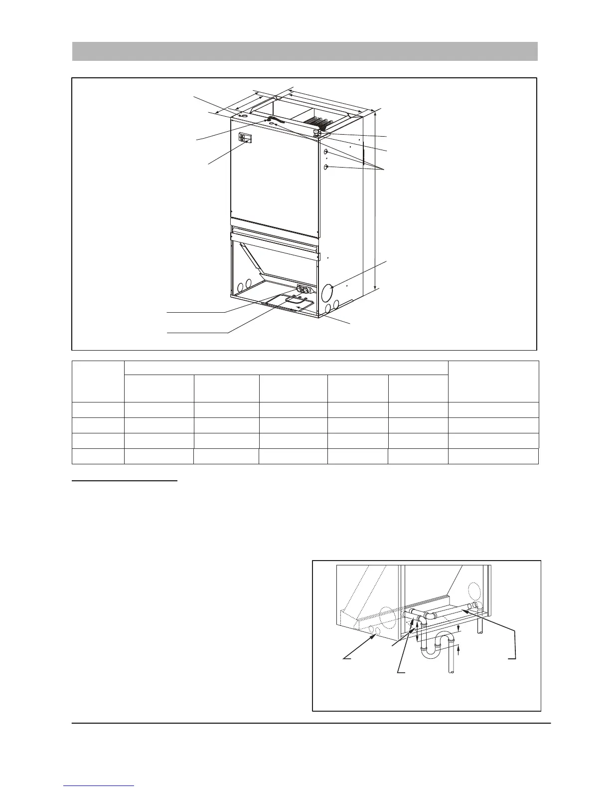
Figure 1 - Dimensional Drawing with Circuit Breaker
Table 1 – Dimensional Data
A170625
Model Size
Dimensions- In. (mm)
Unit Weight /
Shipping Weight
Lbs. (kg)
Unit Height
H
Unit Width
W
Unit Width
W1
Unit Depth
D
Unit Depth
D1
PSC 18K/24K 36-1/2 (928) 20-1/2 (521) 17-2/5 (442) 15 (381) 9-1/2 (242) 86 / 101 ( 39 / 46 )
PSC 30K/36K 39-1/2 (1004) 22 (559) 18-4/5 (478) 19 (483) 9-1/2 (242) 101 / 123 ( 46 / 56 )
ECM 18K/24K
36-1/2 (928) 20-1/2 (521) 17-2/5 (442) 15 (381) 9-1/2 (242) 79/ 95 ( 36 / 43 )
ECM 30K/36K 39-1/2 (1004) 22 (559) 18-4/5 (478) 19 (483) 9-1/2 (242) 97/ 119 (44 / 54 )
INSTALLATION
Step 1 — Check Equipment
Unpack unit and move to final location. Remove carton,
taking care not to damage unit. Remove protective sheet
metal from the base of the unit, if equipped. Inspect
equipment for damage prior to installation. File claim with
shipping company if shipment is damaged or incomplete.
Locate rating plate on unit. It contains information needed to
properly install unit. Check rating plate to be sure unit
matches job specifications. A front access panel is provided,
which permits ac
ce
ss to blower assembly and electrical
controls for removal and servicing.
NOTE
: Minimum clearance of 21” (533 mm) is required in
front of access panel for servicing only. Installation clearance
from combustible materials is 0” (0 mm) from cabinet and
supply
-
air duct (plenum included). Ensure there is adequate
space on top of unit for refrigerant line connections and on
bottom of unit for condensate trap. (See
Figure 1
and
Figure 2
.)
Step 2 — Mount Fan Coil
Fan Coil Mounting Options
The fan coil comes standard with two different options for
mounting: wall mount or frame mount. Both mounting options
require the unit to be level from side to side and from front to
back in order to allow condensate to properly drain from the
unit. Failure to do this will result in condensate leaking out
from the unit, potentially causing structural damage to the
surrounding support structures, drywall, carpet, etc. around
the unit. Also, both mou
nting structures require the ability to
accommodate a minimum of load of 150 pounds. Failure to
do this will cause damage to the support structure and
potentially damage the unit.
Figure 2 - Condensate Drain
A13011
PRIMARY
DRAIN
2" / 51mm
MIN DRAIN
ALTERNATE
DRAIN EXITS ON
SECONDARY
DRAIN
(TRAP EXTERNAL
TO UNIT)
NOTE: Use plastic pipe from
condensate pan to
exterior of fan coil.
2" / 51mm
MIN
EITHER SIDE OF UNIT
All units are vertical upflow only.
Equipment shown with field-installed electric heat.
Low voltage
connection
Breaker switch
(comes with
accessory
electric heater only)
D1
D
W1
W
H
Return air opening
High voltage connection
7/8” (22 mm) dia
knock outs
(both sides of unit)
Some heater sizes may
require a conduit larger than
the 7/8” (22 mm) opening;
in this situation the high-voltage
connection opening should be
enlarged to fit conduit.
Vapor line comection
copper (sweat)
Liquid line comection
copper (sweat)
Auxiliary drain connection
3/4” (19 mm) female
pipe thread (fpt)
Primary drain connection
3/4” (19 mm) female
pipe thread (fpt)
Front return shown. Units
may also be installed as
bottom return. See the
applications section for
more detail.
NOTE:Hand tighten only
High voltage connection
1-1/8” (28 mm) dia
knock outs
Fresh air intakes,
4” (101.6mm) dia
knock outs
Remove the screws and
the access plate for drain
lines service.