12 Index of Figures
ARIADNE Knock Control 29
12 Index of Figures
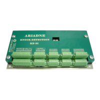
Figure 1: ARIADNE, HEINZMANN’s Knock Control Unit .................................................. 5
Figure 2: Normal combustion, cylinder pressure without knocking ...................................... 8
Figure 3: Uncontrolled combustion, cylinder pressure with heavy knocking ........................ 8
Figure 4: Typical Knock Sensor, Bosch-Type ....................................................................... 11
Figure 5: ARIADNE functional Overview ............................................................................. 11
Figure 6: ARIADNE quick diagnostic display ....................................................................... 12
Figure 7: Stand-alone Knock Control Unit ............................................................................ 14
Figure 8: Fully integrated Knock Control Unit ..................................................................... 15
Figure 9: Sensor dimensions .................................................................................................. 17
Figure 10: Mounting Instructions .......................................................................................... 18
Figure 11: Knock Sensor on cylinder head ............................................................................ 19
Figure 12: Different Knock Sensor position while testing .................................................... 20
Figure 13: Power lines in a typical screw fitting ................................................................... 20
Figure 14: ARIADNE Wiring Diagram ................................................................................. 25
Figure 15: ARIADNE Dimensions ......................................................................................... 27

 Loading...