24
9 Electrical installation
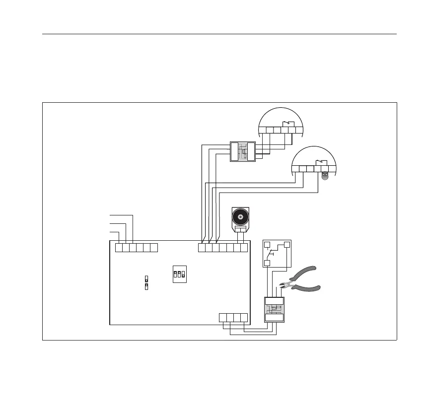
9.6.5 Connection with line surveillance (DIP 1 ON) and two detector stubs (DIP 2 ON)
The system is operated with two smoke switch stubs and with an external manual button. A line
surveillance unit with termination module (AM 142) and a magnet are installed according to DIN
EN 14637. DIP switches 1 and 2 must be set to ON.
L
N
PE
NC 1
COM 1
NO 1
+ 24V
GND
ORS
K
B
THM+
THM -
+ 24 V
HAT
Reset
GND
EN 14637
2 Stiche (2 Stubs)
Al.Speicher (al.storage)
FSZ Basis
=
OFF
=
ON
+
-
THM
ORS/TDS
+
13
2
BUS
-
65
4
RD
BK
WH
YE
+
+
-
-
<
>
>
>
AM 142
ORS/TDS
+
13
2
BUS
-
65
4
S
Ö
L
HAT
AM 142
RD
BK
WH
YE
+
+
-
-
<
>
>
>
1
23
ON
+
-
THM
magnet
(termination
stub)
To prevent a short-circuit,
remove the red and black
connection wires.
Fig. 9: Example connection with line surveillance


 To Next Page