If you are Installing
an Automatic System
The basic difference between the manual system just
outlined and an automatic system is the use of a motor-
ized three-way valve. This three-way valve is operated
by a differential control which uses sensors to determine
if the solar system is warmer or cooler than the pool
water. In this way it can shut the solar system off when
cloudy conditions exist and thereby generate the opti-
mum performance from your solar investment. It also
allows you to select a maximum pool water temperature
so the solar system doesn’t overheat the pool. It ac-
complishes this by the use of a sensor on the roof and
a sensor installed into the pool plumbing. The directions
included with the automatic system components will
direct you in the installation of the control and sensors.
The three-way valve will be installed as described on
the previous page and observing the note above.
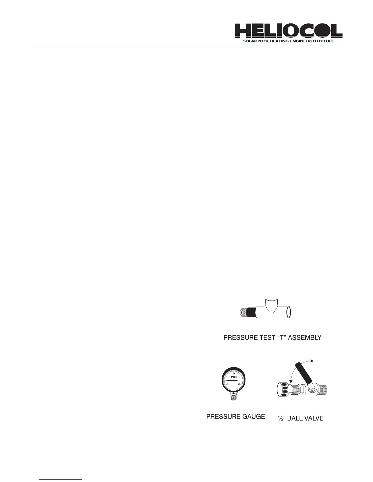
Pressure Testing the Heliocol Solar System
Pressure testing the entire solar system provides for a
trouble-free installation and takes only about fteen min-
utes. Any weak PVC glue joints, ttings or pipe, any im-
proper collector clamp connections, will be evident while
the system is put under 40 to 50 pounds of pressure.
1. Allow ample time for all glue joints to dry completely.
Use this time to wrap up things and to clean up the job
site.
2. Wrap the threads of the 142 pressure test “T” Assem-
bly, 140 ½” ball valve and 141 pressure gauge with Tef-
lon tape. Temporarily replace the 121A vacuum breaker
with the 142 pressure test “T” assembly. Thread the 140
½” ball valve and pressure gauge into the pressure test
“T” assembly.
3. Attach a garden hose to the ½” ball valve. Make sure
the ½” ball valve is in the off position.
4. Turn the solar system on to allow the pool pump to
completely ll the solar system. (If the pool pump is not
operational, shut off the ball valve on the feed line and
use the garden hose to ll the system.)
5. Once the solar system is completely full of water, turn
off the pool pump or turn the three-way valve to by-pass
the solar system. Quickly turn off the ball valves on
both the feed and return lines.
6. Turn on the city water to the garden hose and open
the ½” ball valve on the pressure test “T” assembly until
the pressure gauge reads 40 to 50 PSI and then turn off
the ½” ball valve. Turn off the city water.
7. With the system under pressure, check the whole
system for any leaks. A drop in pressure on the pressure
gauge indicates a leak in the system.
8. If there are leaks, open the ball valve on the return
line to relieve the pressure. Repair any leaks. Repeat
the pressure testing procedures as needed.
9. Return the system to normal when through with
pressure testing. Be sure to open both ball valves
and replace the pressure test “T” assembly with the
vacuum breaker.
20
(142)
(141)
(140)