signal source in order to avoid damage to
the amplier.
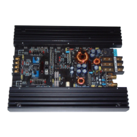
If you want to change the input sensitivity of the
channel pairs use the two Input Level controls
(see page 14 point 9; Input Level). The settings
of the controls affect both the lowlevel (Line
Input) and the highlevel speaker inputs
( Highlevel Input)! If the Highlevel Input is used
with a standard car radio we recommend an in-
put sensitivity of roughly 9 Volts - turn the con-
trol from min position to 1/3 position - 11 o’clock
position.
4. Connecting the loudspeaker outputs
The loudspeaker outputs can be connected
directly to the wires of the loudspeakers. Never
connect any of the loudspeaker cables with the
chassis ground as this will damage your ampli-
er and your speakers.
Ensure that the loudspeakers are correctly con-
nected (in phase), i.e. plus to plus and minus
to minus. Exchanging plus and minus causes
a total loss of bass reproduction. The plus pole
is indicated on most speakers. The impedance
of each channel must not be less than 2 Ohms
(4 Ohms in bridged mode), otherwise the am-
plier protection will be activated. Examples
of speaker congurations can be found on
page 17.
5. Connection to power supply
Make sure to disconnect the battery before
installing the HELIX G FOUR!
Connect the +12 V power cable to the positive
terminal of the battery. The positive wire from
the battery to the amplier power terminals
needs to have an inline fuse at a distance of
less than 12 inches (30 cm) from the battery.
The value of the fuse is calculated from the
maximum total current draw of the whole car
audio system (G FOUR = max. 60 A RMS at
12 V power supply). If your power wires are
short (less than 1 m / 40”) then a wire gauge of
16 mm² / AWG 6 will be sufcient. In all other
cases we strongly recommend gauges of 25 -
35 mm² / AWG 4 – 2!
The ground cable (same gauge as the +12 V
wire) should be connected to a common ground
reference point (this is located where the neg-
ative terminal of the battery is grounded to the
metal body of the vehicle), or to a prepared met-
al location on the vehicle chassis, i.e. an area
which has been cleaned of all paint residues.
6. Connecting the remote input
The remote input (REM) has to be connected to
the radio remote output if the ampliers pre-am-
plier inputs are used as signal inputs. We do
not recommend controlling the remote input via
the ignition switch to avoid pop noise during
turn on/off.
If the Highlevel Input is used this input does not
need to be connected as long as the car radio
has BTL output stages.
16
Installation
 Loading...