Do you have a question about the HELIX P SIX DSP MK2 and is the answer not in the manual?
Read manual carefully to prevent damage and injury during installation.
Connect to vehicles with 12V/24V negative terminal to chassis ground.
Switch between setups or reset the device.
Indicates operating mode and chosen setup of the DSP.
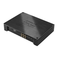
Connects amplifier to PC for configuration.
Interface for remote controls and accessories.
Optical input for digital stereo signals (SPDIF).
Adjusts input sensitivity of low- and high-level inputs.
RCA inputs for pre-amplifier signals.
Connects to factory or aftermarket radio speaker outputs.
Switch setups (1 sec hold) or erase memory (5 sec hold).
Shows DSP setup (green/orange) or no setup (red flash).
Connect to PC for configuration using DSP PC-Tool software.
For accessories like remote controls, configurable via software.
For digital audio signals (SPDIF), supports 12-96 kHz.
Adjusts low/high-level input sensitivity; crucial for amplifier protection.
Connects 6-channel pre-amplifier signals; sensitivity adjustable.
Connects directly to speaker outputs; sensitivity adjustable.
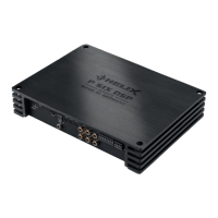
Speaker outputs for channels A-D; impedance ratings.
Lights red if analog inputs are overdriven.
Lights red for faulty fuse, green for normal operation.
Connect to a common ground reference point or vehicle chassis.
Used to turn on/off amplifier, connected to head unit remote output.
Connect power cable to the positive terminal of the battery.
2-channel pre-amplifier output for external amplifiers.
Used to turn on/off external amplifiers connected to line outputs.
Speaker outputs for channels E-F; impedance ratings.
Use RCA cables to connect pre-amplifier outputs from car radio.
Connect directly to loudspeaker outputs of OEM or aftermarket radios.
Mandatory to adapt sensitivity to signal source for amplifier protection.
Change sensitivity range by repositioning internal jumpers (Jumper A, B).
Diagrams showing jumper positions and their corresponding value ranges.
Details on jumper settings for extended input sensitivity ranges.
Specific jumper settings for RCA inputs E and F for AUX.
Connect optical digital output; automatic detection or manual switching.
Connect +12V/+24V power cable to battery terminal with inline fuse.
Connect to radio remote output for amplifier turn-on.
Deactivate automatic turn-on via switch inside device if needed.
General settings via DSP PC-Tool software before first use.
Connect speaker wires correctly (phase, impedance) to outputs.
Use Rem Out to supply remote signals to external amplifiers.
Simplify connection to OEM/aftermarket radio using optional cable.
Install optional HELIX Extension Cards for added features.
Download and install the latest DSP PC-Tool software from the website.
Connect amplifier via USB, turn on, and start the software.
Features 96 kHz sampling rate for extended audio bandwidth.
Operates with 12V or 24V supply voltage without modification.
Reduces power consumption when no input signal for 60 seconds.
Maintains supply voltage during engine crank even with low battery.
Automatically switches to digital input when signal is detected.
Prevents diagnostic errors and feature loss with OE radios.
Details power output per channel at different impedances.
Lists types and ranges for inputs, outputs, and voltage.
Covers frequency range, DSP resolution, sampling rate, and converters.
Covers legal regulations; excludes overload or improper use.
No liability assumed for damages caused by handling errors.
| Channels | 6 |
|---|---|
| Amplifier Class | D |
| DSP Processing Power | 295 MHz |
| THD+N @ 4 Ohms | < 0.05% |
| Total Harmonic Distortion | < 0.05% |
| Signal-to-Noise Ratio | > 100 dB |
| Damping Factor | > 200 |
| Highlevel Inputs | Yes |
| Fuse | 30 A |
| Crossover | Yes |
| RMS Power (2 Ohms) | 150W x 6 |
| Bridged RMS Power (4 Ohms) | 3 x 300 Watts |
| Input Impedance | 10 kOhm |
| Input Sensitivity | 0.2 - 4 V |
| Digital Inputs | 1 x Optical |
| Frequency Response | 10 Hz |
| Dimensions (W x H x D) | 7.5 x 2.5 x 10.5 inches |