Do you have a question about the HELIX M FOUR DSP and is the answer not in the manual?
Follow carefully all installation instructions to prevent damage and injury. Product checked for proper function.
Disconnect battery's negative terminal to prevent damage, fire, or injury. Professional installation is recommended.
Install in a dry location with air circulation. Secure to a solid surface. Check for hidden cables/lines behind mounting.
Install in 12V negative ground vehicles only. Use main fuse near battery and suitable cables with correct fuses.
Plan wire routing to avoid damage. Protect cables from crushing/pinching. Avoid routing near noise sources.
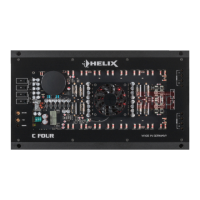
Connects audio signals from radios or digital sources.
Outputs for connecting amplifiers, speakers, and remote signals.
Interfaces for PC connection, remote control, and accessories.
Buttons, LEDs, and switches for device operation and status indication.
Connections for power supply, remote activation, and grounding.
Switches between 10 memory locations for sound setups or performs a device reset.
Turns on/off connected amplifiers. Activated automatically upon amplifier boot.
Highlevel and Line inputs for audio signals. Crucial to adapt input sensitivity.
Connects amplifier to PC via USB for configuration using DSP PC-Tool software.
Indicates the DSP's operating mode. Green means ready for operation.
Multifunctional input for HELIX accessory products, e.g., remote controls for amplifier adjustment.
SPDIF input for digital audio sources. Supports sampling rates from 12 to 96 kHz.
Processed 6-channel pre-amplifier output (6V RMS) for connecting additional power amplifiers.
Activates/deactivates the automatic turn-on feature for Highlevel Inputs. Default is ON.
Outputs for connecting speaker systems. Minimum impedance 2 Ohms (4 Ohms bridged).
Indicates amplifier mode: Green for ready, Red for malfunction.
Connect the +12V power cable to the battery positive terminal. Min. 10 mm² / AWG 8 cable recommended.
Remote input for turning the DSP on/off. Connect to head unit remote output.
Connect ground cable to a common ground reference point or vehicle chassis.
Connect RCA/Cinch outputs of head unit to pre-amplifier inputs. Remote input required for auto turn-on.
Connect directly to loudspeaker outputs of OEM/aftermarket radios using speaker cables.
Connect optical digital output to amplifier. Manual activation via remote control is configured.
Disconnect battery. Connect +12V cable to battery positive with inline fuse. Use appropriate wire gauge.
Connect REM input to radio remote output. Auto Remote switch deactivates Highlevel auto-turn-on.
Configure general DSP settings with PC-Tool software before first use to avoid damage.
Adapt input sensitivity to signal source to avoid amplifier damage. Use 'Input Gain' menu.
Connect directly to loudspeaker wires. Ensure correct polarity and impedance (min. 2 Ohms).
Supplies remote signals to external amplifiers to avoid on/off switching noises.
Diagram showing signal flow from inputs to virtual channels and then to speakers.
Diagram of system configuration with multiple HELIX amplifiers for a complex audio setup.
Diagram of system configuration with two HELIX M FOUR amplifiers for a 2-way front system.
Download and install the latest DSP PC-Tool software from the Audiotec Fischer website.
Connect the amplifier to the PC using the provided USB cable. Use extension cable for longer distances.
Turn on the amplifier, then start the software. Software updates automatically if needed.
Configure the M FOUR DSP using the PC-Tool software. Hints available in 'Sound Tuning Magazine'.
Set car radio volume to minimum during first start-up. Configure general settings before connecting devices.
VCP is a multi-stage signal processing concept for perfect configuration of complex sound systems.
VCP adds processed channels, offering cross-channel EQ, multi-way speaker configuration, and SFX.
Influences tonality of all assigned output channels in multi-way configurations simultaneously.
SFX like RealCenter/Augmented Bass Processing tied to virtual channels for flexible routing.
Enables functions like 'Rear Attenuation' for separate virtual channel volume control via remote.
Route input signals to respective virtual channels using input matrices. Define virtual channel names and properties.
Assign virtual channels to physical output channels in the 'Outputs' menu. Configure channel-specific settings.
Configure virtual channels and SFX in the 'Virtual' menu. Influence tonality via equalizer, polarity, time.
DSP sound effects available when VCP is enabled. Certain hardware/software settings required.
Assign input signals to virtual channels and route 'Virtual E – Front Center Full' to desired output channels.
StageXpander/ClarityXpander settings affect virtual channels 'Front L Full' and 'Front R Full'.
Assign input signals to virtual subwoofer channels for bass processing. Route to desired output channels.
Permanently assigned to Line Outputs I/J when VCP is inactive, regardless of output naming.
Links to output channels receiving 'Subwoofer1' or 'Subwoofer2' signals in 'Virtual to Output Routing'.
Sets delay time for DSP switching on/off. Factory setting is 0.2 seconds.
Provides ten memory locations for sound setups. Toggle between locations with optional remote.
Controls temporary deactivation of remote output during sound setup switch. Default is ON.
Adapt ADEP.3 circuit to OEM radio's diagnostic mode for class SB output stages to avoid distortions.
Powerful CoProcessor for monitoring/communication. Enables software upgrades and 10 memory locations.
Avoids OEM radio diagnostic issues without loading speaker outputs.
Maintains constant supply voltage even during engine crank voltage drops.
Reduces power consumption when no input signal is present for >60s. Turns off connected amplifiers.
Details power output at various impedances and the amplifier technology used.
Lists available input types (RCA, Highlevel, Optical) and output types (Speaker, RCA, Remote).
Specifies input sensitivity ranges and impedance for RCA/Cinch and Highlevel inputs.
Specifies RCA/Cinch output voltage and the device's frequency response range.
Details DSP resolution, power, sampling rate, and type.
Specifies signal converter types and signal-to-noise ratios for inputs.
Details THD, damping factor, and operating voltage range.
Specifies idle current, max remote output voltage, and fuse type/rating.
Lists additional features like ADEP.3 circuit and physical dimensions (H x W x D).