10
1. Determine mounting position
and mark mounting points accor-
ding to attachment dimensions
given above.
2. Drill pilot hole with 3 mm dia.
bit and then bore out to 8 mm.
Protect drilled metal parts with rust
protection paint.
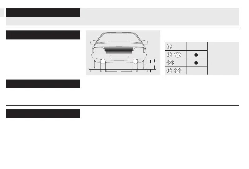
Attachment dimensions:
For upright/pendant mounting.
Lamps should neither vibrate nor
extend higher than the bonnet and
must be fi tted symmetrically.
Tools required:
Mounting steps:
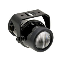
3. Remove lamp set, press rubber
grommet in from inside and install
stabilization ring (Fig.1; 2).
4. Preinstall bracket and tighten
bolts hand-tight.
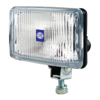
1. Adjusting frame
Accessories, see Fig. page 6
(not included with kit)
• Ruler
• Combination pliers
• 10 mm open-end or box wrench
• Drill with 3, 8, 12 mm dia. bits
• Screwdriver for recessed-head
screws
D
CC
A
B
(also see
”One more tip”)
The table shows the possibilities
permitted in the various countries:
2. Wiring harness with relay