INSTALLATION AND OPERATING INSTRUCTIONS
4211-70 G
Rev. 3
5/9/14
R.D. LD
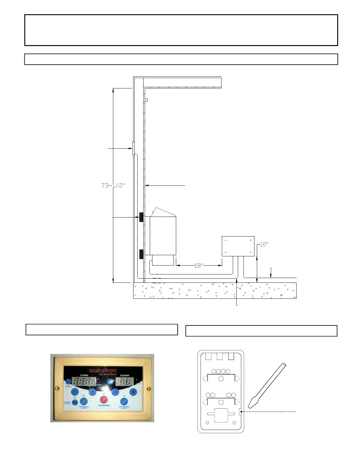
DIAGRAM 3
DIAGRAM 4
DIAGRAM 5
Back of
sensor
Insert screwdriver tip here to
unsnap sensor cover from
sensor.
Note vertical orientation of
Page 4
SaunaLogic Control
Sensor protective cover.
Locate top of sensor 2" from
ceiling and directly above of
heater.
Control Box (CB PK-1) can be outside of the sauna
room or installed inside sauna room.
If inside sauna room see diagram below for spacing
requirements.
Minimum spacing.
Maximum
spacing.
CB PK-1
Control Box
Power
Input
Minimum
ceiling
spacing.
15' Low Voltage wire
provided with control.
tongue and groove
2x4 supports
SaunaLogic
7' SJTW Wire provided
with heater
 Loading...