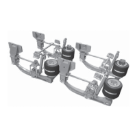
PRIMAAX
®
EX / PRIMAAX
®
for Volvo Vehicles
17730-254 39 Component Replacement
NOTE On PRIMAAXEX models built after September 2010 or equipped with the enhanced U-beam
Assembly, it will be necessary to remove the existing sealant and tamper resistant cap for
the support beam/cross tube connection to proceed with the bolt removal. Carefully remove
sealant with a hand scraper to prevent damage to the U-beam assembly.
2. If applicable remove the existing sealant and tamper resistant cap for the support beam/
cross tube connection to proceed with the bolt removal. Carefully remove sealant with a
hand scraper to prevent damage to the U-beam assembly.
3. Remove the support beam/cross tube connection bolt from the end of the beam.
4. Remove the end cap (if equipped).
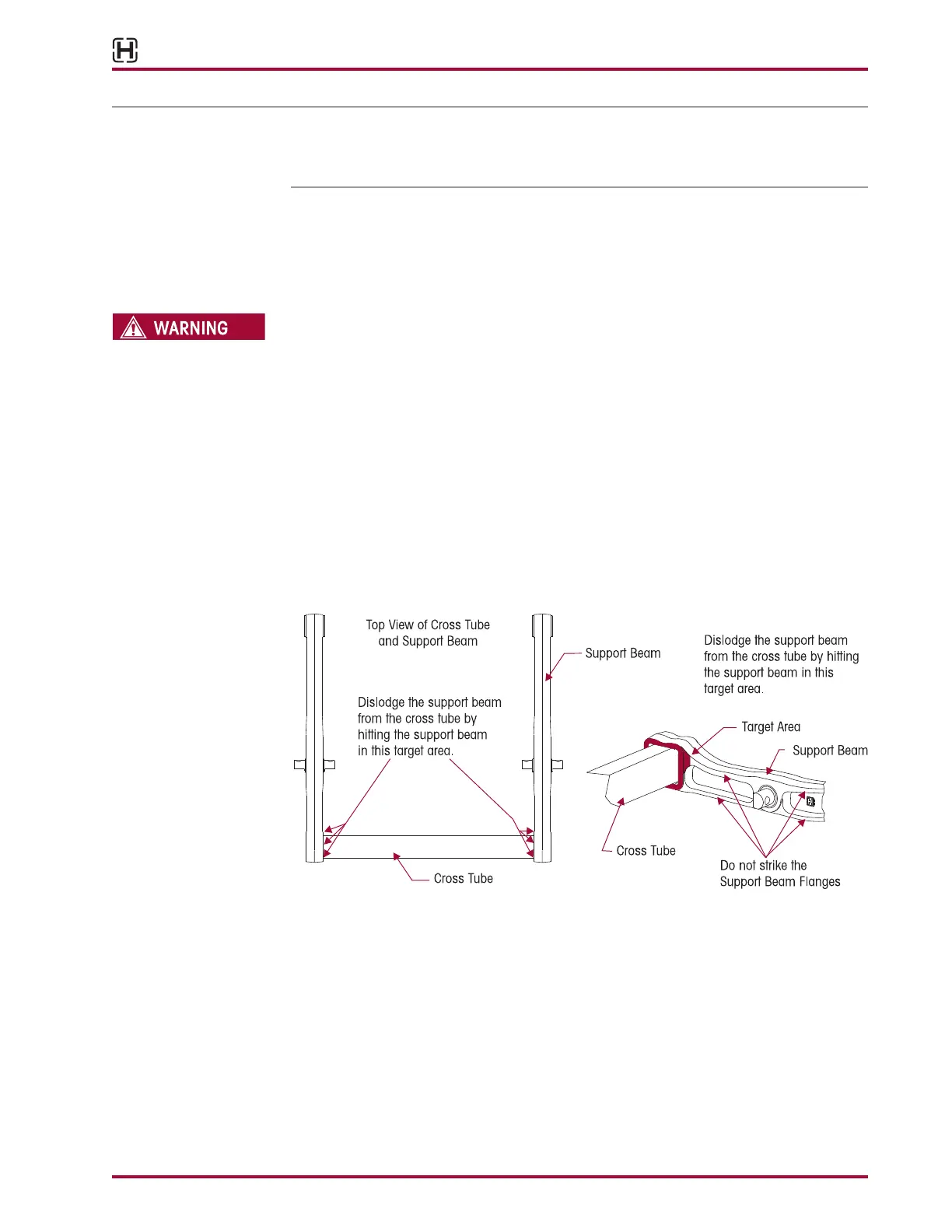
WHEN SEPARATING THE U-BEAM ASSEMBLY, PROTECT THE CROSS TUBE BY PLACING A PIECE OF
PLYWOOD AGAINST OR CARDBOARD AROUND THE CROSS TUBE. CAREFULLY DISLODGE THE CROSS
TUBE FROM THE SUPPORT BEAM WITH A LONG HANDLED SLEDGE HAMMER BY APPLYING BLUNT
FORCE ON THE SUPPORT BEAM DIRECTLY IN FRONT OF THE INBOARD TOP CORNER JOINT. ALL
BLUNT FORCE MUST BE APPLIED FLUSH TO THE THICKEST PART OF THE SUPPORT BEAM. FAILURE TO
STRIKE THE SUPPORT BEAM SQUARELY MAY RESULT IN COMPONENT DAMAGE, PREMATURE FAILURE
AND VOID WARRANTY, SEE FIGURE 8-13.
5. Place a piece of plywood or cardboard around the cross tube prior to applying blunt force
to the support beam.
6. Dislodge the support beam from the cross tube by hitting the support beam directly in front
of the inboard corner joint. The support beam and cross tube joint requires shock load on
the support beam, at the joint, to dislodge the two components. All blunt force must be ap-
plied flush to the thickest part of the support beam at the inboard corner joint, see Figure
8-13. Continue striking the support beam until it is completely dislodged from the cross tube.
FIGURE 8-13
7. Inspect all components for any damage or wear and replace as necessary.
8. Clean any loose debris or foreign material, and if applied remove all old sealant for inspec-
tion and reassembly.
9. Place the support beam in a shop press on top of a receiving tool with both ends of the
support beam squarely supported on the press bed.
10. Mark the clocking position of the D-pin bushing on the support beam with a paint stick, see
Figure 8-14.
11. Install the D-Pin Removal Tool centered on the D-Pin bushing, see Figure 8-15.