PRIMAAX
®
EX / PRIMAAX
®
for Volvo Vehicles
17730-254 41 Component Replacement
DO NOT ASSEMBLE ANY QUIK-ALIGN JOINT WITHOUT THE PROPER FASTENERS. USE ONLY HENDRICKSON
COATED FASTENERS TO SUSTAIN THE PROPER CLAMP FORCE. FAILURE TO DO SO CAN CAUSE LOSS OF
VEHICLE CONTROL, PROPERTY DAMAGE OR PERSONAL INJURY AND VOID WARRANTY.
ENSURE THAT THE QUIK-ALIGN FASTENERS TORQUE VALUE IS SUSTAINED AS RECOMMENDED IN
TORQUE SPECIFICATIONS SECTION OF THIS PUBLICATION. FAILURE TO DO SO CAN CAUSE LOSS OF
VEHICLE CONTROL RESULTING IN PERSONAL INJURY OR PROPERTY DAMAGE.
NOTE Use new QUIK-ALIGN pivot bolt kit (see Parts List Section of this publication) for any axle
alignment or disassembly of the QUIK-ALIGN connection. This ensures that the proper clamp
load is applied to the connection, to ensure the joint will not slip in service.
SERVICE HINT Each frame hanger will have a pair of QUIK-ALIGN collars. Note which type of QUIK-ALIGN collar
is removed from which frame hanger location to facilitate the assemble process. Any eccentric
(with the square drive feature) QUIK-ALIGN collar should be mounted on the outboard side of
the frame hanger. Axle thrust angles can only be corrected on frame hangers equipped with
eccentric QUIK-ALIGN collars.
6. Verify the correct QUIK-ALIGN collar (eccentric/concentric) is in the correct location as
noted in the disassembly procedure.
7. Install QUIK-ALIGN connection with new Hendrickson fasteners and snug to about
50-100
foot pounds torque, DO NOT tighten at this time. The final torque must be done after the
alignment is complete.
8. Spread the support beams to facilitate the installation of the cross tube.
9. Install the cross tube into the support beam one side at a time.
10. If equipped, install the end cap making sure the “V” notch in the end cap is on the top.
FIGURE 8-20
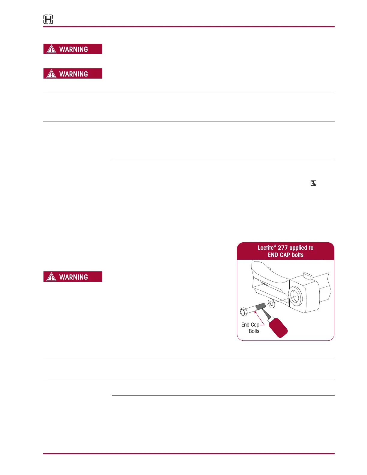
11. Apply Loctite 277 to the
7
⁄8" fastener and in-
stall in end hub. DO NOT tighten at this time,
see Figure 8-20.
THE WEIGHT OF THE SUPPORT BEAMS AND CROSS
TUBE ASSEMBLY IS APPROXIMATELY 225 POUNDS.
CARE SHOULD BE TAKEN AT REMOVAL AND
INSTALLATION TO PREVENT PERSONAL INJURY OR
DAMAGE TO COMPONENTS.
12. Position the support beam and cross tube
assembly on a floor jack equipped with a 4"
support plate.
13. Raise the support beam and cross tube
assembly until the D-Pins engage in the bot-
tom cap.
SERVICE HINT It may be necessary to rotate the QUIK-ALIGN eccentric collars to pull the axle forward to allow
the full engagement of the D-Pins into the bottom caps.
SERVICE HINT It may be necessary to raise or lower the front of the differential to allow the D-Pins to engage
in the bottom cap. Use a drift pin if necessary to align the D-Pins with the bottom cap.
14. Install the D-Pin fasteners, installing them from front to back, see Figure 8-21.