Retrofit Kit Instructions Digital display air flow velocity HERAsafe HS/HSP
Valid: 12.2001 50072901 5
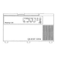
9. Assembly flow transducer:
Drill a hole (Diameter of hole 25 mm) for the flow transducer
(Pos. 3) in the middle of the frame [1] according to drawing
HS 9 50067608 (Pos.18)
HS12 50066318 (Pos. 19)
HS15 50067725 (Pos. 20)
HS18 50067325 (Pos. 21),
and additional drill two threads M4 for holding.
Saw and cut the neck of mounting flange.
Insert flow transducer (slit in the direction of the air flow ! ), screw on with raised countersunk head
screw (Pos. 4) and seal the joint between work chamber and rear wall canal with sealant.
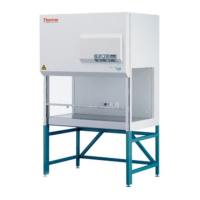
Drill a one hole for the cabel duct of the flow transducer
into the front of the unit between motor and the other
cable ducts, diameter of hole 16 mm.
Insert rubber grommet (Pos. 5) and seal all with sealant.
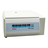
Wire the flow transducer with new wire set
(Pos. 17) according to wiring diagramm 50065658 - page 6, (Pos. 1)
and mount it with cable support (Pos. 14) and
cable tie (Pos.15).
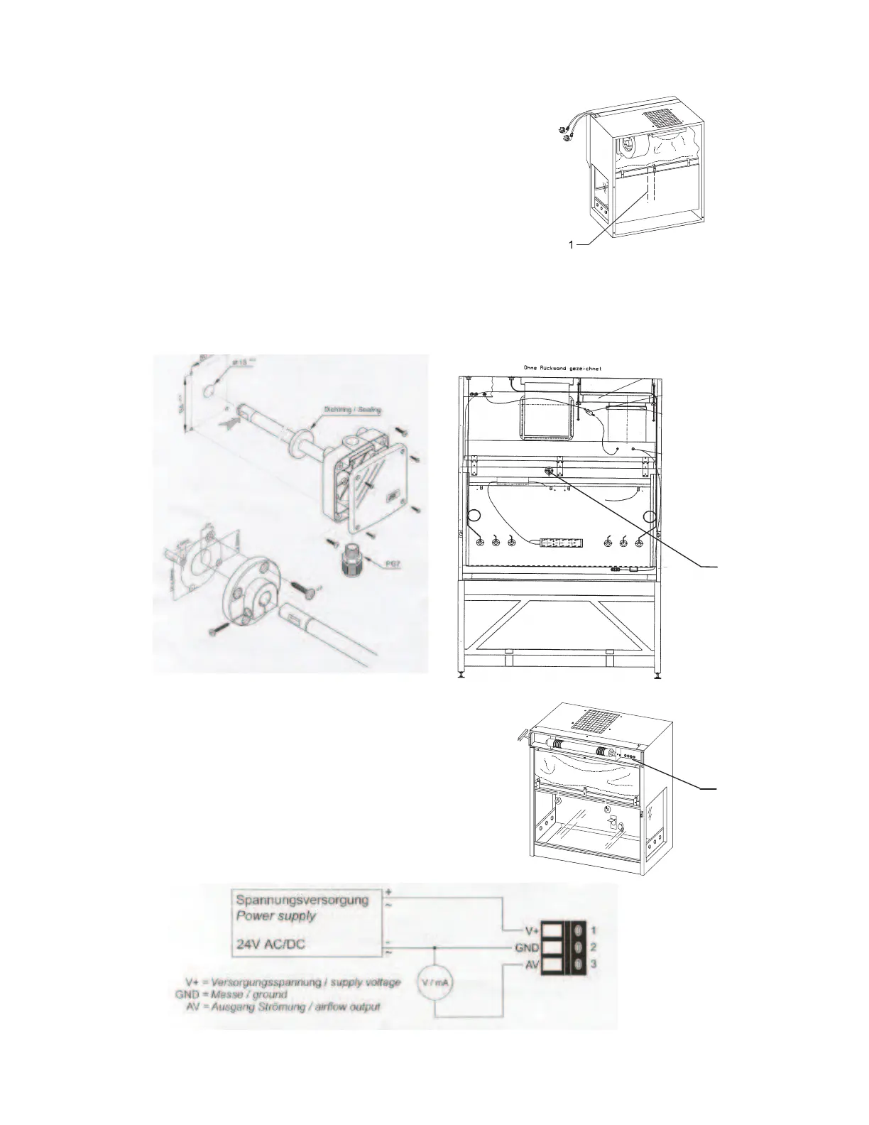
Connection of the screw terminal: