Retrofit Kit Instructions Digital display air flow velocity HERAsafe HS/HSP
Valid: 12.2001 50072901 6
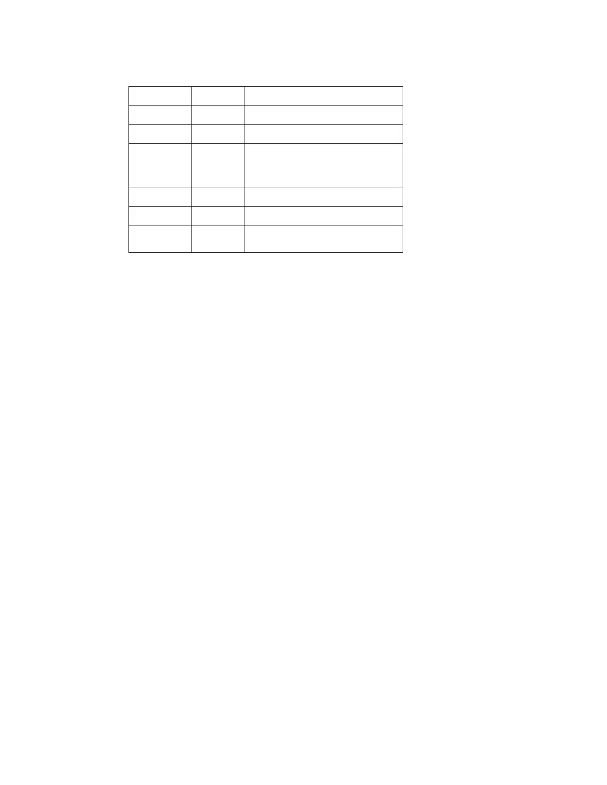
Adjustment of the parameter
Parameter Value describtion
l n P 0 - 10
Input sensor 0 - 10 V
d P - - - -
Point position
0 - XX
Calibration lower reading
(Reference value minus reading with
switched off ventilation)
X - 10
Calibration upper reading
L I 0
Limit measurement range
F i L t
Filter set on the mean value of the
last measuring results
Close the lid of the flow transducer.
10. Assembly downflow filter
Build in plenum frame and plenum bag.
Insert the downflow filter so that the side with the filter labeling is visible.
Install the retaining screws. The filter seals must be flush with the plenum frame and with the floor of
the inspection chamber.
11. Closing the inspection chamber
Thoroughly remove all sealant residues from the edges of the cover and from the housing frame.
Secure the cover with the six retaining screws.
Seal the joint between the cover and the housing frame with sealant.
Secure the guide rails with the hood brackets using the retaining screws.
Push the cable tensioners over the studs and secure them with the two nuts.
Adjust the window at the housing frame.
Push the stabilization spring [5] of the cables up or down until it is at half the height of the cover.
12. Assembly and sealing of the rear wall
( see assembly instruction 50046989 )
13. Assembly control unit
( see assembly instruction 50044533 )
14. Closing the control box.
Connect all cable on the control panel according to wiring diagram 50065658.
Place the cover on the control box and secure it with the five screws.